It feels like I didn't achieve as much as I had planned this month. Some unforseen distractions put a hole in my schedule, and anticipated distractions appeared as scheduled. But some significant steps have been made.
Continuing with the wings, the next step was to deal with the stall warner holes in the right wing. Since my avionics will utilize an Angle Of Attack (AOA) display, it was determined that the stock stall warner blade and horn would be unnecessary. But I still needed to close the holes in the wing and finish off the access hatch in the right wing. Just for practice, I did assemble the stall warner as well. After prepping and priming all parts, I riveted the hatch doubler to the skin and riveted on the nut plates for the cover. The prepunched holes in the leading edge needed to be dimpled and plugged with flush rivets; another somewhat nerve-wracking job. Because the wing was already assembled, I had to use the close-quarters dimple dies with the rivet puller, then very carefully set some small rivets in the holes with a bucking bar and the rivet gun. One mistake could have ruined the leading edge skin which would have been a HUGE disaster, but my caution paid off with a smooth plugged leading edge. After assembling the components of the stall warner it was set aside for later storage or possible sale.


I ordered an Avery aluminum pitot mast from Aircraft Spruce and received my Garmin pitot/AOA probe from Aerotronics, along with some wiring for lights, servos and pitot heat. I did a lot of homework on the pitot mast installation and refined the supplied template with a photoshop drawing before tackling the daunting task of cutting the hole in the skin for the mast, and it went well. The Avery mast base plate is attached to inside of the bottom skin and notched to fit around the back flange of the spar of the left wing. Some builders add additional support for the back side of the mast plate; others say it isn't necessary. Van's Builder Support supplied the tie-breaker advice that it would be a good idea to add some support, and suggested a triangular piece attached to the adjacent inside rib. I made some card stock templates to determine shape and angles, and made one out of aluminum sheet. I made sure that the plate was held level with the top of the ribs and spar flange to assure that I drilled the rivet holes in the correct place. When fabrication was complete I clecoed the spar mast to the wing structure and the skin and was happy with the result. I considered some lightening holes in the rear support, but I don't have the tooling to emboss any reinforcement shapes into the piece and it's a light part so it will remain as is. Eventually I should probably prime it, too.


At this point, my course was unclear. The work that remained on the wings consisted of figuring out the wingtip mounting, installing the lighting in the wingtips and running wiring and pitot/AOA lines before attaching the bottom skins. There was also the momentous step of fitting the wings to the fuselage, setting the incidence and drilling the rear spar hole. I toyed with the idea of completing the wingtips and lighting fabrication, and drilled the installation holes for the Suntail strobe in the rudder bottom fairing.


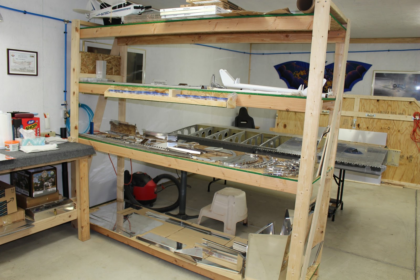
The installation of the wingtip lighting turned out to be a major undertaking that required 40 pages of instructions, and I wasn't sure I was ready for that yet. It would also be easier to do the initial wing fitting without the pitot tube/mast, wiring and bottom skins installed. So I decided to see if it would be feasible to do the wing installation in the main shop. After doing a lot of measuring, I figured I would just barely have room to accomplish the task if I rearranged the shop. I moved the shelving over by the built-in workbench and moved the paint racks to the right, towards the west wall. I moved the wing tables end-to-end with the outboard ends of the wings as close to the wall as possible and double checked the measurements to make sure I would have enough room for the wings to fit on either side of the fuselage. It would be tight, but it was feasible. With help from my neighbor James, I relocated the wings to the wingstand and got the fuselage moved from the garage bay to the main shop.


At this point I was motivated to start working on the fuselage. The construction manual states that the instructions for builders of the QB fuselage should start at page 42, but it is also strongly recommended that builders go through the entire manual to check off steps done by the factory, making sure we have the big picture and that no steps were left undone. This turned out to be very good advice, as I found several things that required making decisions that would have hung me up much later in the build. There are many aspects of the quickbuild kits that have you wondering "Why did they do that?" or "Why didn't they do that?" and some of those points require a lot of research to figure out.
On initial close inspection, I found myself worried about certain removable panels that were installed with flush phillips head screws that didn't want to come out, and it looked like the threads were corroded. It didn't help that most of my phillips head screwdrivers are worn out, and I didn't want to butcher the screw heads. Eventually I found some good tools to use and was able to safely remove the screws. The threads weren't corroded, and screws into nutplates are supposed to bind a little, so all was good.
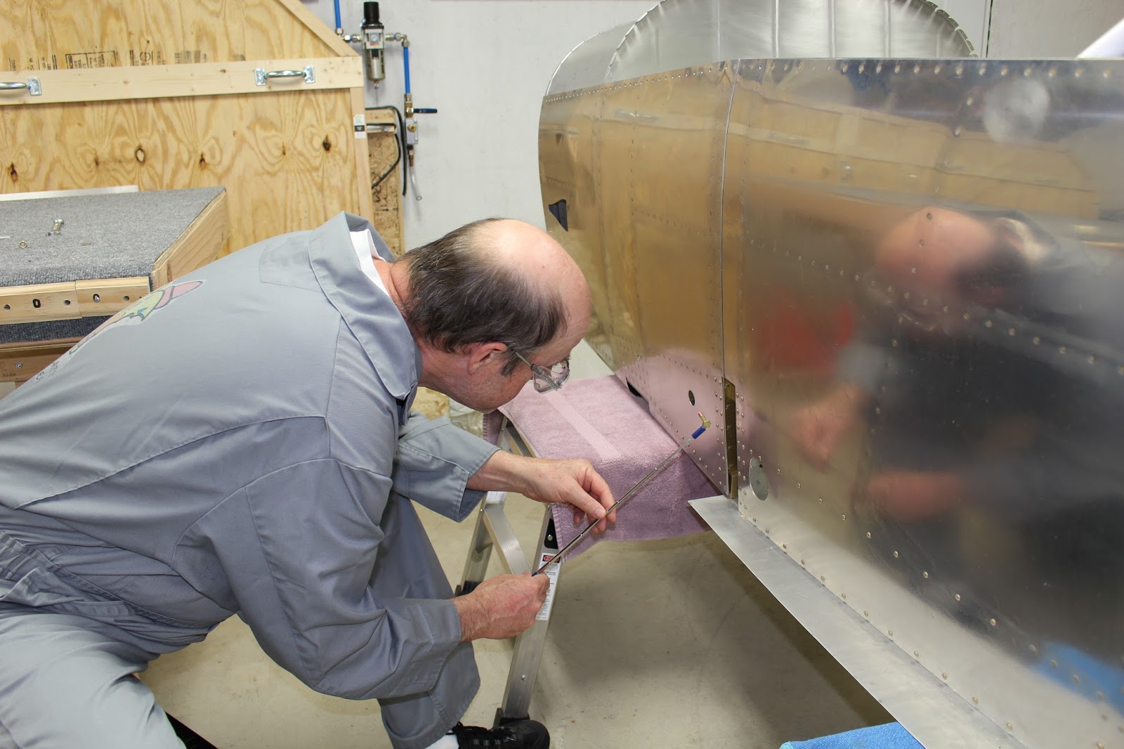
The first important task was to comply with Service Bulletin 16-12-16 regarding twelve bolts that were missing from the center section spar box. All twelve bolts are installed in the forward part of the spar box; the bolts are supposed to be inserted fore-to-aft, with the washers and nuts on the inside of the spar box. To perform this task I had to suspend the weight of the fuselage from the rolling stand, remove the wooden inserts from the spar pockets and rolling stand uprights, roll the stand out from underneath the fuselage, replace it with the aluminum work stands and lower the fuselage. This allowed me to be able to access the bolt holes for the twelve missing bolts from the spar pockets. This was another daunting task to do alone, but the cherry picker made it possible. Even with the wooden inserts removed, access proved tricky because the slot for the wing spar pocket is too narrow for my whole hand to enter. There is also a center opening on the front and back of the spar box, but they are small. Getting the washers and nuts in place with the limited access inside the spar box seemed almost impossible. Other builders of finished and flying aircraft have had to cut 1" holes in several places along the top of the spar box and the bottom fuselage skin to get the job done. I knew that was an option for me if I chose, but I wanted to avoid cutting those holes if I could. I decided to insert the bolts from the inside of the spar box using a magnetic stick, which was fairly easy to do if I used a flashlight to shine through each hole as a guide. That made washer and nut installation easy and also allowed me to mark them with torque seal when the job was finished. Although research showed this method has been used by other builders, I wondered why it wasn't suggested by the factory. It seemed to me that the only downside was breaking the cardinal rule of installing all aircraft assembly bolts fore-to-aft. I got the bolts, nuts and washers in place but didn't tighten them until I got approval from Van's Builder Support the next day. In order to get a wrench onto the nut inside the spar box, I had to fabricate a special tool using a torque bar with a clawfoot socket inserted into a 2' cheater bar fabricated from steel box tubing. The actual tightening would be a two-man job, so I enlisted James' help again to hold the clawfoot cheater bar on the bolt heads while I tightened the nuts using a torque wrench set to proper spec. Once all elements were in place, the tightening went quickly, and I was glad to have that important step completed.


One of the steps I discovered in the manual review involved building the aileron trim assembly. Research indicated that some builders omit aileron trim, and that it's not as important in an RV-8 because of its tandem seating layout. But other builders say it's a good thing to have, and if I was to have it in my airplane, I should install it now. The aileron trim is a sub-kit with its own instructions and blueprints; the prints are smaller in scale than standard prints, but still usable. Assembly went well, overall, but I did make one somewhat foolish mistake. There are two brackets that need to be mounted to the left and right seat ribs in the bottom of the fuselage using blind rivets. During initial assembly of the right bracket, I checked the blind rivets I was using, and discovered they were flush rivets... but the manual didn't mention countersinking. So I drilled out the two I already installed, dimpled the right bracket... and learned that I couldn't dimple the holes in the rib because of limited access, and I didn't have a close-quarters dimple die set for #30 holes. I ended up lightly countersinking the rib holes with the thought that the blind rivets would pull the parts together well enough for a non-structural assembly. While pulling the rivets, the mandrels didn't seem to be breaking as cleanly as usual. No big deal; the bracket was secure, and I filed down a few exposed mandrel points when the job was done. The left bracket required some preassembly before mounting, so I didn't install it until the next day... and that's when I discovered my error. The rivet call-out was for a standard blind rivet, and I thought I had been grabbing from that section of my blind rivet bin... but I had actually grabbed from the adjacent bin, which were very similar... but they were flush-head blind rivets. That explained all my questions regarding the assembly. Why did I need flush rivets? I didn't. Why didn't the instructions mention dimpling or countersinking? Because neither were required. Why did the mandrels break off weirdly? Because they weren't the right rivets. That's a whole lotta red flags I managed to miss. The left bracket installation went well. I hadn't dimpled that bracket, so the standard blind rivets fit well and the mandrels broke predictably. I considered drilling out the right bracket rivets and replacing them, but I talked myself out of it. The installation may have been technically incorrect but it was a secure assembly of a non-structural part that was better left alone. I may also rethink my pulled rivet bin arrangement. Having the bins labeled on the lid made it easy to pick from the wrong bin when the lid was open. In retrospect, the thought train that followed that simple mistake seems rather absurd. Another lesson re-learned: When In Doubt, ALWAYS DOUBLE CHECK YOUR RIVET CALL-OUT.


One step that is required for standard kit assembly of the fuselage bulkheads is fitting the bulkhead tops and aft top fuselage skin to help align the bulkheads for assembly. Although this isn't necessary with a quickbuild kit, I couldn't resist the urge to test fit them to get a glimpse of what the fuselage would look like in a more complete stage. It could be considered a waste of time, but I found value in the motivation provided, and thinking ahead on assembly is always beneficial.


There are numerous decisions that are suggested in the earlier sections of the manual, and battery location is one of them. The best location of the battery depends on the specifications of your particular aircraft: engine and prop selection, primary mission of the aircraft, anticipated loading, etc. My own parameters prompted me to opt for an aft battery installation. Assembling the aft battery tray was fairly simple, but several aspects stretched out the process. I got most of the parts prepped, primed and assembled, but the two nut plates needed for the hold down bolts required domed-head rivets of an unusually small size, and they weren't listed anywhere in the inventory. Van's sent a batch of the required rivets quickly enough. I wanted to finish the parts with a thick top coat of Rust-Oleum gloss black paint for corrosion resistance, but I had to wait until I had installed the nut plates before I could paint the tray. There were also tight clearance issues with setting those small domed-head rivets in the special nut plates, and I had to modify one of my rivet sets to be able to squeeze the rivets squarely. Trying use the rivet gun on those little rivets seemed too risky, and the results justified the modification. I finally got the tray painted and I'm letting the paint cure thoroughly before installing it in the fuselage.


The missing rivets issue brings up something else that I'm dealing with at this stage. When I got the quickbuild kits I was very thorough in the process of taking inventory. I went through every bag of hardware and did counts on every washer, nut, bolt, fastener and a lot of other small parts. I found I had a few extra, and was missing a few, based on the quantities on the packing list. I addressed the shortages and Van's sent out the missing items. Now I'm finding out that there are some parts listed on the plans that aren't included in the inventory, such as the small rivets for the battery tray. Another example: there is a section of the fuselage that requires a total of 34 screws, washers and nuts to be installed around the gear towers that were not installed as part of the quickbuild kit. This has been a problem for QB builders that don't inspect the manual prior to page 42 when they realize that these parts are called for on page 40. They assume that the screws were left out for a reason and continue with the build. Later on, they realize the screws should have been installed a long time ago, and now they have a lot of ancillary equipment inside the gear towers that will make getting the nuts and washers on those screws a nightmare. Having read other VAF threads on the subject and reviewing earlier steps, I discovered the instructions at a good stage in my build. I started gathering the required screws, washers and nuts, only to find that the washer was an unusual size; I needed a total inventory of 39 of those washers that I was aware of at this point (34 for the gear tower screws and five for the stall warner kit), but Van's inventory only included 15 total. I spent hours scouring that inventory sheet, making sure I hadn't missed a batch of that washer size in some mystery bag. Later I learned that other QB builders only had 15 of those washers listed in their inventory. I could have bothered Van's about the missing washers, but in this instance it was easier for me to just add the washers to another order I needed to place from Aircraft Spruce. It cost me less than a dollar and that way they'll arrive sooner. Van's does such an incredible job of putting these very complex kits together that a few missing washers or rivets seems far too trivial to complain about. Nobody's perfect; every builder can certainly attest to that. To me, it's just part of our learning curve.
At this point I've finally caught up to my "starting line" on the fuselage; page 42 of the construction manual. There are previous instructions that I will have to refer back to later on; I've notated them in the margins. The complexity of building an aircraft allows some steps to be done at various stages of the build according to builder preference; other steps must be done in a very precise sequence. It's one of the many things that all builders must learn on their own. The next step for me in the construction manual is the fitting of the landing gear legs. It requires that the fuselage be flipped upside down for assembling the components and aligning the gear legs, but like setting the wing incidence, this is one of those operations that can be done at different stages. It's easier to flip the fuselage now and get the work done, but then the gear should be removed to finish out the fuselage, mount the empennage, install the engine and cowling and fit the canopy before installing the gear legs permanently. That works for me, so in preparation I uncrated the Grove gear legs I've been storing for so long. I did an inventory of the parts supplied, comparing them to stock Van's parts and making a note of what parts will need painting or powdercoating. Flipping the fuselage is not something I'm equipped to do myself at this point; I've yet to set up a rotisserie for the wings or fuselage. The cherry picker won't help here and I don't have the engine mount installed, so it will require at least 3 or 4 people to safely invert the fuselage on the work stands. I'm hoping to get some helpers scheduled for next weekend. In the meantime I can get some work done on the seat backs and flooring.


This is an interesting point of the build for me; a mix of drudgery and excitement. The drudgery of smoothing, prepping and painting many large parts again... and the excitement of climbing into the fuselage, sitting on the seat, making airplane noises and dreaming of wonderful future flights. I'm expecting that will provide some pretty strong motivation. Stay tuned...