This entry might be a bit of a letdown, given the hype I gave it in the previous post. Much like last month, I find myself writing this as a way to remain productive while waiting on weather.
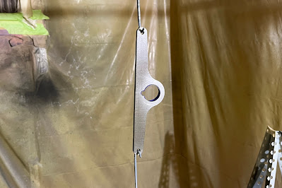
February began with more work on the upper intersection fairings. The inside of the right fairing's leading edge was relieved a bit more and a small expansion slot was cut to try to improve overall fit. I tried to improve on the methods I used on the lower intersection fairings for closing up the aft end. The nut plates and screws I used are draggy, ugly and bigger than they need to be. For the upper intersection fairings I decided to use tee nuts with prongs, set into one half of the aft skirt and secured with screws through the other side. Sourcing the hardware at the local hardware store was problematic; I could find small tee nuts, but no screws that would work with them. I ended up going with metric hardware because I could find very small tee nuts and matching round head screws. The body of the tee nut extended through both flanges; rather than grinding them shorter I used washers as shims. The tee nuts were installed into the bottom halves for aerodynamic reasons; the parts seem to come together well and the extra flange material was removed. Once installed, it became evident that having the screws come in from the top made it very awkward to tighten them because of limited space. A right-angle screwdriver has to be used for two out of three screws on each side (these have been replaced with cap screws as noted later in this blog). I may end up making some custom intersection fairings in the future. The current parts don't fit as well as I had hoped but I don't want to invest a lot of time in them right now. Let's get this thing flying first.


Winter weather slowed down meaningful progress but I tried to stay busy. The second 15 gallon fuel jug arrived and both jugs were brought to the hangar. The bottom cowl support was finished; bolt holes were drilled through the post and folding flange to hold all the parts securely in the correct positions. I designed a tailwheel pocket jig that would fit around the tailwheel tire and hold it securely. I intended to use it for several applications, including a tailwheel stand designed to hold the fuselage in a level attitude, and also as part of a hitch that would allow me to tow the airplane by the tailwheel with the Ford Explorer. The prototype jig was carved out of a solid wooden board; during testing it promptly broke in half along the grain. If I had used plywood it wouldn't have failed. I submitted a crude blueprint to the St. Pierre Machine Shop to have it made out of plate steel.


The cowling was reinstalled and the prop was fully unmasked, which was pretty cool to see for the first time. I continued to ponder ways of assembling a proper tailwheel stand for doing the weight and balance. To hold the fuselage in a level attitude the tailwheel had to rest on a firm surface about 36-3/4" off the floor. I knew my shop work benches were built to a three-foot height and I had built the C-frame table to match that height. Measuring the C-frame table revealed that its height would be perfect with the top carpet layer loosened and swung to one side. It would be easy to raise the tail with the Tail Mate, lift the tailwheel out of the Tail Mate platform, slide the C-frame table underneath and set the tailwheel on the table. The airplane could be moved back and forth with the tail on the table while getting the main wheels onto the scales; once positioned, the tail could be lifted and the third scale could be slipped under the tailwheel. It was the ideal solution. I studied the weight and balance instructions, then copied, reformatted and printed them out. The weighing procedure was discussed with several fellow EAA Chapter 194 members Gus Warren, Harry Manvel and Curt Martin. They all volunteered experienced assistance; eventually I set a date with Harry and Curt to weigh the aircraft. All remaining components and parts were installed on the airplane. The forward baggage floor was screwed down securely; it would remain in place for the first engine start. The aft wing fairings were added to the wing roots. The remaining screws were inserted in the side panels. The aft baggage shelf and bulkhead were installed loosely with screws in place and the seats were installed. To avoid a lot of unnecessary disassembly and reassembly, the front cockpit console covers were set in position without screws. I brought the Hooker harnesses back to the shop and made the necessary modifications to the inserted anchor bushings, grinding them down to fit between the mounting brackets in the fuselage. They were returned to the hangar and placed in their correct positions. The plane was now ready to weigh.


On the appointed day I arrived early to attend to some final details. The front halves of the wheel fairings were removed, the tire pressures checked and the front halves remounted. The tail was raised to level the fuselage and plumb bobs were suspended from the leading edges of each wing. The airplane was then positioned so that the leading edges aligned with lines previously drawn on the hangar floor. From there, I could extrapolate the position of the datum line and mark it on the hangar floor using a sharpie and straight edges. All weight and balance calculations are made in relation to the datum, an arbitrary reference point or geometrical plane selected by the designer normally placed in front of the aircraft nose so that all arm measurements will be positive. Van's set the datum line for the RV-8 at 70" forward of the wing leading edges. Van's has designed distance values from the datum line to the wheel axles that should be confirmed by each builder. There is only so much accuracy that can be obtained measuring from lines drawn on a hangar floor with a tape measure, but at least I could determine how close my airplane would be to the intended design specs. Harry and Curt arrived with the scales and ramps and we discussed the plan of action. First, the tailwheel was lowered to the ground. We determined that the plane would be pushed forward to mount the main wheel scales. A ramp and platform were positioned in front of each main wheel and the plane was carefully pushed onto the platforms, which had built in chocks to prevent the wheels from rolling off the front edge. With the main wheels on the platforms, the ramps were moved and the main wheel scales placed behind the platforms. The tail was raised with the Tail Mate; I lifted the tailwheel off of the Tail Mate and held it up while Curt and Harry, moved the Tail Mate clear and slid the C-frame table under the tailwheel into a position that would allow for some movement fore and aft. The plane was carefully rolled backward onto the main wheel scales, the tailwheel scale was placed under the tailwheel and we confirmed that the plane was completely level in that position. The plane was rolled off the scales and back onto the platforms; all three scales were set to zero, the plane repositioned onto the scales and readings were taken. This procedure was repeated to get a second set of readings for confirmation. Prior to weighing, we had all taken guesses as to what my aircraft would weigh. I guessed 1100 lbs.; Curt guessed about 1135 and Harry guessed about 1154. The weight on the right main wheel was 517 lbs., the left main wheel was 524 lbs. and the tail wheel was 63 lbs. The total came to 1104 lbs. I won. With the weighing completed, we got the plane off the scales, aligned the wing leading edges with the hangar floor line and checked the arm measurements for the main wheels and tailwheel The main wheels came in very close to factory spec at 68.75"; the tailwheel was a bit longer at 251.75". Now I had all the measurements needed to do any and all CG calculations for my aircraft. Another milestone reached. Later on that day, it occurred to me that in all the excitement I had forgotten to take a photo of the actual scale readings. I do have a photo of Curt and Harry staring at the scales, so at least I can prove I have witlesses - I mean, witnesses. I'm fairly certain that they'd be willing to testify if required, and am very grateful for their help.


With the weight and balance done, I could begin to configure the aircraft to prepare for the first engine start, followed by the airworthiness inspection. I kept the plane in a level attitude to make it easier to work inside the cockpit. The aft baggage panels were removed and I thought I'd go ahead and attach the aft seat shoulder harnesses. My new DAR Matt Tomsheck had acknowledged that some of the Hooker harness components would have to be left disconnected to allow proper inspection, but he wanted both sets of shoulder harnesses secured in place. Although access would be awkward, I thought that connecting the aft shoulder harnesses would be easy. I was wrong about that. Before I could bolt the harness anchors to the anchor straps that are riveted to the aft fuselage skin, the bolt holes needed to be reamed slightly and the bolts inserted from the top. That was easy enough, but it looked to me that there was no way to get the bolt into the hole from the top; the skin was too close for the bolt to be positioned to go into the hole. I didn't want to try to bend the straps downward because I feared that I'd deform the skin, so I tried securing the anchors with the bolts coming up from underneath and the washers and castle nuts on top of the anchor straps. I did manage to get the nuts and washers on but I found it almost impossible to align the castle nut slots with the cotter pin holes in the bolts. Keep in mind, I'm doing all this while lying on my back, wedged into the aft baggage compartment with my arms restricted and the flap weldment digging into my back. Just getting in and out of that position in the fuselage was a nightmare; handling tools and parts totally by feel and having to use a mirror to check the alignment made the job seem just plain ridiculous. I took a break for the day, went home and did some more research. Other builders had no problem getting their bolts in from the top, so when I got back to work I unbolted the anchors and tried deflecting the anchor straps slightly. It turned out to be easily done with no risk of skin damage and the bolts slid into place. I felt like a fool for wasting two hours trying to do it wrong, but that's a feeling every first time builder knows well; it's the price paid for knowledge. The next attempt at bolting on the anchors went better, but I had to swap the standard washers for thin washers to get the correct alignment to secure the cotter pins. Eventually I had the anchors bolted, cotter pins in place and the shoulder harnesses routed, buckled and secured.


When the winter weather got nasty, I stayed home and crunched numbers. I filled out all the weight and balance sample sheets in the Van's manual using the data on my aircraft and used Photoshop to print out official sheets. I also made custom templates for future use, filled in an Excel spreadsheet provided by another builder for an RV-8 and worked on the ForeFlight weight and balance program on my iPad. The continuous repetition of the process helped me absorb it and gain some semblance of fluency.


When weather allowed, I tackled the task of removing the empennage fairings, intersection fairings, wheel fairings and wing fairings. While the tail was still on the table, I disconnected the tailwheel springs and removed the steering arm. It had originally been treated with WD-40 prior to installation, but over the years some rust was beginning to appear. I brought the steering arm and some of the fairing parts back to the shop for painting. The weather was still below freezing and I pondered ways to heat the wood shop paint booth with the shop heater. I've been thinking about how to heat the wood shop reliably for years; the optimal way was to install a second heater in the garage and run ducts to the wood shop, but that isn't financially viable right now. I've thought of elaborate ducting to bring heat from the shop heater to the wood shop, but nothing off the shelf seemed to fit the bill. So I thought I'd try using two of the shop paint booth frames to set up a closed tunnel between the shop door and the wood shop door. Once the wood shop was warmed up, the steering arm was prepped and painted with Rustoleum Rust Reformer flat black paint. When the tailwheel pocket jig was completed by St. Pierre, I picked it up and test fit it at the hangar; while I was there I reinstalled the steering arm and reconnected the springs. I bought a 3/4" bolt, lock washer and nut for the hitch and six M3 socket screws for the upper intersection fairings. I brought the pocket jig back to the shop, painted it and bolted it to the hitch receptacle. The socket screws were placed in the tee nuts on the upper intersection fairings. I'll shorten a metric Allen wrench for tightening these, which should be much easier to deal with than the screws.


That's where I'm at right now. Still battling the weather, keeping the driveway and hangar door clear and watching the forecasts like a hawk in hopes of having the first engine start happen next week. The fuel tanks will need to be refilled and I'm planning to have local avionics expert Danny Foxx help me with calibrating the fuel gauges during that process. I've also spoken to Jason Smith at Aerotronics and gone over what other calibration steps I can take prior to first flight. I'll want to get some Permatex Ultra Black RTV sealant and reseal the baffles but I'm uncertain about applying it in a cold hangar; maybe that can wait until later. In the meantime I'll get this post published and cross that off the list. To paraphrase John Belushi as Jake Blues: "The next post will be great... you'll see!" Stay Tuned!