This post will be shorter than most because it only covers a month filled with distractions and frustration. The distractions were mainly vehicular in nature. I spent some time working on the new (old) Yukon, chipping away at the long list of squawks. I sold the Gold Wing, which allowed me to get the work started on replacing our driveway. But I couldn't be without any motorcycle at all, so time was spent looking for a new (old) bike. Looked at a neat classic Honda, but it needed more work than I wanted to do. So I bought a 2001 Kawasaki KLR650 dual-sport bike. I had bought one new in 2001 that was sold in 2004, so it was like getting reacquainted with an old friend. In the process, I learned that old friends get older, too. Those bikes are known to be reliable as rocks, but this one won't idle when warm. Probably needs a tune up and carb overhaul, but I really don't want to launch into that project right now. It can wait.
The homebuilder's meeting that Leo Knowlden and I hosted went well. Eleven members of EAA Chapter 113 made the journey north to Clarkston to visit my shop and Leo's shop to ask questions and explore our handiwork. It was a good morale booster and hopefully educational for all. Shunsuke Shibata took some photos, and I made a short time lapse video of the event and shared it on my YouTube channel. See the link below the photos.


Homebuilders Meeting Video


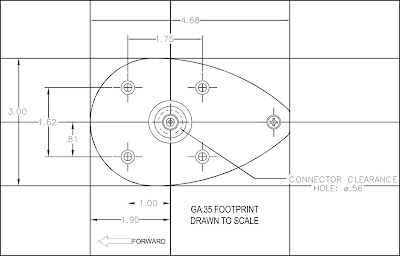


After dismantling the temporary lighting platforms on the fuselage, I got back to work on the forward top fuselage skin, preparing to mount the Garmin GA 35 GPS antenna puck and a pair of ventilation fans. This was another phase of the build that had me filled with trepidation because it was literally uncharted territory. Jason Smith from Aerotronics had discussed the antenna location with me; we had decided it should be mounted on the top forward skin in the glareshield area just behind the windscreen. My plan was to also mount two small cooling fans on either side of the puck to vent hot air from behind the instrument panel. I had to determine the best location for the fans and antenna puck in relation to the windscreen, but I had no idea just where that windscreen would end up on the forward top skin. I also had to determine the size of the fans I wanted to use and what specs they should meet and order them from Digi-Key. Another looming worry was how to get the top forward skin riveted down. Usually the rivets are bucked by reaching up from underneath behind the panel, but having the avionics assembled on the panel meant that access for bucking the rivets along the instrument panel and baggage bulkhead was very limited. I considered using all blind rivets, but that might prevent the forward top skin from being watertight over all those expensive avionics. I knew I would have to use at least a few blind rivets because of the access issues, but I thought if I could remove the large Garmin GDU 460 EFIS screen it would allow a rivet bucker to reach through the opening in the panel to buck solid rivets in most of those rivet holes. Van's had recommended using Cherry Max blind rivets where necessary for structural considerations. That would require the rivet holes to be reamed out to a larger size and possibly re-dimpled or machine countersunk. Again, the assembled avionics made this prospect more complicated. It was a lot to think about, so I spent a lot of time thinking. I had made some preliminary layouts on the skin for the GPS puck and fans, but had to do some research on where that windscreen might end up on the skin. I asked for input from VAF members and Terry Lutz sent me a photo of his glareshield and windscreen with a ruler laid in place. That gave me a probable dimension from the instrument panel rivet line to the base of the windscreen, and a possible location range for the puck and fans. Garmin's installation instructions for the puck recommended fabricating a doubler plate to reinforce the skin underneath, so I cut one out of some spare sheet stock. I checked my previous layout drawings for installing the puck and found some measurement errors but at least the screw and antenna cable hole dimensions were correct, so the doubler plate would still work. I made more accurate drawings and printed up templates.


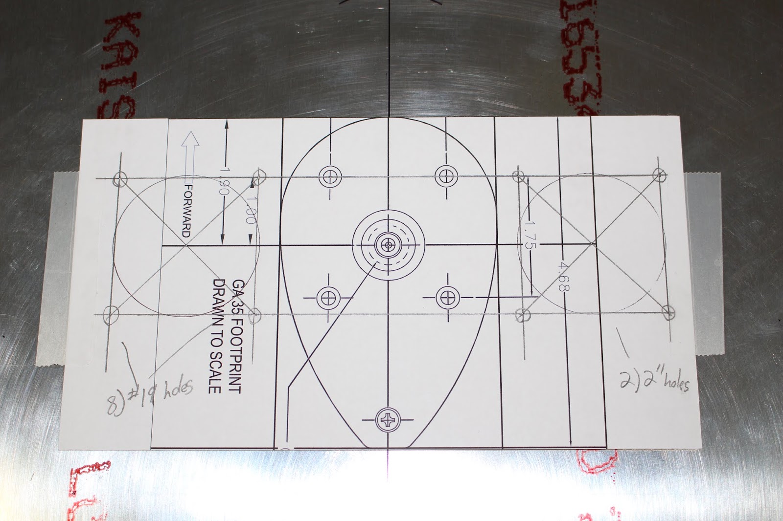
The skin was laid onto the fuselage to check the layout against the location of the panel avionics. Once I was comfortable with the placement of the template, I drilled pilot holes for all the screw holes, the antenna cable hole and the fan openings and used the pilot holes to cleco the skin to a piece of wood, securing it for drilling the larger holes. I double checked everything with the templates, components and doubler before drilling all holes to their final size.


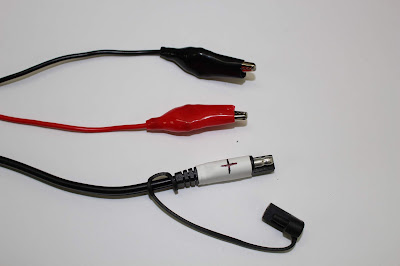
The fans I chose were typical 12V computer fans made by Orion; I chose the 60 millimeter square size and a thin depth; I also ordered screens to fit between the fans and the skin to prevent anything from being able to fall into the fan openings. When I mounted and tested them, one fan was inop; Digi-Key sent a free replacement. While I waited for the replacement to arrive, I fabricated a test lead harness that would allow me to use the aircraft battery installed in the aft fuselage to bench test the fans. Initially I used ring terminals and larger alligator clips; I later modified the harness with a quick-connector and smaller, more precise alligator clips.


When the new fan arrived, I wired the two fans together in parallel and tested them together. The new ran for about two seconds before failing. I called Jason and he confirmed that my wiring was correct and that the fans should not have failed. I ordered two more fans and discussed the issue with Digi-Key tech support. They asked me to return the two failed fans for inspection, and had me double check the voltage supplied by the battery. The multi-meter indicated a consistent 12.6 volts.


When the replacement fans arrived I tested the replacements and the original, recording the tests on video. All three worked, so I wired two fans together in parallel and attached Molex connectors, soldering all connections and sealing with heat shrink tubing. I fabricated positive and ground leads for connecting the fans, mounted the assembly to the forward top skin on the bench and tested it. Once again, only one fan worked. I couldn't believe it. Wiggling wires, the fans briefly worked, one at a time, then both stopped working. I removed both fans from the skin, cut off the connectors and tested the fans separately. Both worked, briefly... and then failed. This time, I could smell that they had fried. So now I had one fan left. I decided to give it a duration test. It ran for less than twenty seconds before failing. That made a total of five fans that had failed completely... this was getting very discouraging. I compiled the photos and video for evidence and conferred with Jason again. He clarified some electrical concepts for me that I hadn't fully grasped. I knew the voltage supplied by the battery was within spec, and suspected I was somehow providing too much amperage to the motors. Jason explained that my logic was flawed; you can't force-feed a level of amperage to a motor; as long as the voltage is correct, a motor will only pull the amperage it requires. Based on that, the motors should not have failed... but obviously, they did. Jason pondered that either the fans were mis-rated... or they were just really cheap fans. I needed to find better replacements, but they had to fit the existing holes in the skin. After more research I ordered two more fans made by Delta that were more expensive, but more durable; water and dust resistant; better bearings; better amp/watt and CFM ratings. I also ordered better screens. Before testing the new fans, I had another conversation with Digi-Key tech support. They suggested putting a diode across the leads of each fan to assure that the voltage was regulated, so two 12V 1W diodes were ordered. While I waited for them to arrive I took care of some other miscellaneous errands. I put the horizontal stabilizer and elevators back into storage in the garage and glued down the alternator lead conduit to the fuselage stiffener in the forward baggage compartment. I also purchased a Tail PICKER-1 from Aircraft Tugs and dialed it in for use on my tailwheel.


When the diodes arrived, I soldered them across the leads for each fan and and sealed them in heat shrink tubing, taking care not to overheat them. I attached new connectors, mounted the pair of fans to the underside of the skin and did another bench test. Success... at last. The Delta fans were thicker and they were louder, but they moved a lot more air. I cut the leads to length and put a ring terminal on the positive lead and a ground block connector on the negative lead. The positive lead was connected to the spare circuit breaker in the avionics block; the negative lead connector was inserted into the ground block and the ground block was reconnected to the ground bracket. I mounted the GPS puck to the top of the skin and clecoed the skin to the fuselage to check the clearances of the assembled components around the installed avionics; it all looked good.


Now it was time to test the fans as installed in the aircraft; I also wanted to test the starter relay. I had been advised to not actually test the starter without a load, so I disconnected the starter cable from the starter. I just needed to hear the click of the relay to make sure it was activating when the ignition key was rotated to "start". When everything was ready I turned the master switch on, and was surprised when the fans came on right away. Because the spare circuit breaker was wired into the avionics block, I expected the fans to remain off until the avionics switch was turned on. They seemed unaffected by the avionics master switch, but were turned on and off by the master switch. Testing the starter relay revealed another anomaly. Master on; key in; rotate to start, and the starter relay activated. Released the key... and the starter relay remained activated, even with the key removed. It would only deactivate when the master was turned off, or the circuit breaker was pulled. That couldn't be right; that would keep the starter running with the key released, which would lead to disaster. More research into both issues was required.
I disconnected the fan harness, removed the forward top skin from the fuselage and removed the positive fan lead from the spare circuit breaker. Reviewing my wiring schematic, I saw that there was another relay associated with the avionics master switch and it had its own circuit breaker. Maybe I could connect the fan lead to that circuit breaker instead. I had another conversation with Jason about the fans and the starter relay. He knew immediately what was going on with the fans. The way the wiring schematic was designed, the avionics master switch provided power to the avionics relay. If the avionics relay ever failed, the system would default to "on" and would remain on until the master switch was turned off. When I tested the fans, I reset the spare circuit breaker but didn't reset the avionics relay circuit breaker. The system interpreted that as a relay failure and bypassed the avionics relay and the avionics master switch. That's why the fans came on with the master switch. With both the spare circuit breaker and the avionics relay circuit breaker reset, the fans would remain off when the master switch was turned on. When the avionics master switch was turned on, the fans would come on. Subsequent tests proved this to be correct.


The starter relay issue had us both puzzled, but Jason suspected the diode wired to the relay might be the cause. We went over the correct testing sequence to troubleshoot the issue. I disconnected the positive wire from the key to the starter relay and removed the diode. I connected the positive lead of the multi-meter to the key wire, grounded the negative lead and rotated the key to "start"; the multi-meter showed 12 volts. When the key was released, the voltage dropped to 0; that told me that the key switch was functioning correctly. I reconnected the key wire to the solenoid with the diode in place as before. I connected the multi-meter positive lead to the starter cable, grounded the negative lead and tested the ignition switch. Key off: 0V. Key to start: 12V. Key released: slight voltage drop to 11V. Not right. Removed diode from starter relay and tested: key and relay both worked as they should. Tested different diode, connected the same way: same erroneous result. Tested with different diode grounded to firewall instead of across the small terminals: key and relay worked correctly. I've seen the diode connection described in differing ways from different sources; based on Jason's information, it shouldn't have mattered. I'm still not sure why the diode across the small terminals caused the fault. But for whatever reason, the problem is now solved, and that's good enough for me.


With the electrical issues sorted, I could start planning to attach the top forward skin. That meant addressing another nagging issue. Over the course of working on the fuselage I'd come to realize that the top part of the quickbuild fuselage canoe was just a bit wider than it should have been. Before I bolted the windscreen support weldment to the fuselage, I had to spread the hoop of the weldment slightly to fit the fuselage. But the instrument panel didn't quite fit right either; another clue that maybe I should have strapped the fuselage to fit the weldment instead of spreading the weldment to fit the fuselage. Now getting the top forward skin to fit right on both the instrument panel and along the fuselage longerons would require pulling the hoop together to pull the longerons into alignment with the instrument panel and baggage bulkhead. I'd used a ratcheting strap to do it before and it worked well enough, but it did take some force and the ratcheting strap couldn't be released gradually... it released with a BANG. That would spell doom for any rivets exposed to a shearing jolt like that. Perhaps I could use a turnbuckle strapped to the hoop ends to gradually pull things together and hold them in position while the top skin was riveted on. The turnbuckle could then be gradually loosened and removed... but that would build a shear stress into the assembly that could cause trouble later. My other option would be to fabricate a shim strap to use along the top flange of the instrument panel to fill the gap. But trying to match drill something like that would increase the likelihood of messing up the existing match drilled and dimpled rivet holes and ruining the parts. I still haven't decided for sure which option is the lesser evil, but I thought I'd experiment with the turnbuckle as a proof of concept. It took some fiddling with the attachment straps, but I was able to get the turnbuckle on and the fuselage pulled into alignment. I also carefully detached and removed the GDU 430 EFIS screen, wrapping and boxing it for temporary storage.


That brings us to the present. The driveway paving was just finished yesterday, so another set of distractions await in the form of back-filling the edges of the asphalt, building up a couple transition areas and leveling out a large mound of dirt in my front yard. There are always more vehicular distractions, daily chores and the call of fun summer activities. But time is short; spring took so long to arrive and the weather has been so erratic that I'm feeling like I'm letting too much time slip by. I've got to get back to steady work on this airplane or I won't get all the desired prep, painting and finishing work done while the weather is warm. I gotta get back to work. Stay tuned!