I dismantled the paint booth at the end of October, and the Arizona trip took up the first half of November. I needed to get the wheels and brakes on the landing gear before flipping the fuselage. This was yet another job that I thought would go quickly, but it took up the rest of the month. The wheel pant fairing brackets required lots of prep work and substantial modification to fit the Grove airfoil gear legs properly. That process took a lot of bending, trimming and numerous test fits before I was happy. The way that the axles, brakes, jack point brackets and wheel fairing brackets come together turned out to be an interesting puzzle. The plans described the installation of Cleveland brakes, but Van's now uses MATCO brakes and wheels, so it took a couple calls to Van's and MATCO to get it figured out, and required additional wheel fairing bracket mods.
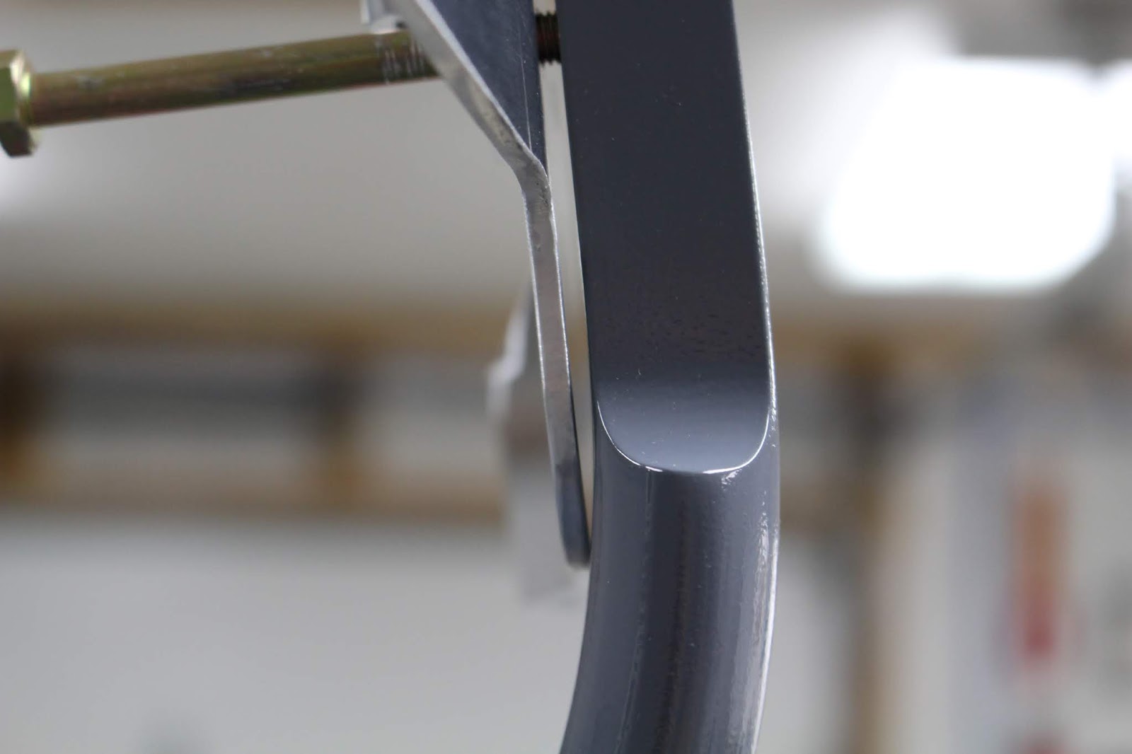


I also discovered a minor issue with one of my jack point brackets. The jack points are an aftermarket accessory that makes it much easier to lift the finished aircraft to change a tire or do brake work. The brackets have a boss with a vertical bolt hole drilled in it for mounting the jack point. On one of my brackets, the vertical hole was not centered. Another phone call to the manufacturer and it was quickly replaced. Once I was satisfied with the fit, the brackets were wash primed and primed.


I needed to double check my alignment before final assembly. This required making spacer blocks, taping them to the axles and stretching a monofilament line or thread from one block to another to check for toe-in or toe-out. I discovered that I had toe-out on both axles; 1/2 degree on the right and 1 degree on the left. The tolerance is 1/4 degree or less, so I had to order axle shims from Van's. When I received them, I realized that they were actually MATCO shims... and that the 1 degree shim I ordered was a caster shim, not a toe shim. More calls; MATCO sent me two more 1/2 degree shims and Van's credited my return of the caster shim. For the recheck, I made more precise spacer blocks, but the results were somewhat inconclusive. It seemed that every time I disassembled and reassembled the components, I'd get a slightly different result. Eventually I got everything within spec and bolted together.


I ordered the wheel bearing grease specified by MATCO, packed the conical bearings with grease and inserted them in the wheels. Since the bearings are not press-fit into the wheels, I had to figure out the best way to get the wheels on and off the axles without dropping the bearings on the floor. With the wheels in place and the axle nuts at the correct torque, I drilled the holes in the axle for the required cotter pins. I also had to figure out how to install the brakes. It was deceptively simple and I should have grasped it intuitively, but because the brakes came assembled and the instructions were slightly vague, it took me a while before I realized the calipers could not be slid over the discs as you would with a car or motorcycle. The stationary pads and spacers must be removed; the calipers are then slid into their carrier shafts and the stationary pads and spacers are bolted back onto the calipers, enclosing the disc between the pads. With the wheels and brakes in place, the brake lines could be fabricated. I ordered elbow fittings and installed them in the calipers and gear legs. After checking the photos of the way other builders have installed their brakes on Grove airfoil gear legs, I realized that they used straight fittings on the calipers and elbows on the legs. My brake lines are longer than theirs, but I like that my brake lines are routed further away from the discs and have a little more length to absorb any slight movement between the calipers and the legs. I wanted to have the jack point brackets anodized but the cost was prohibitive, so I went with anodizing paint. I may change this later, but it will work for now. Once everything was ready, all the components were assembled, torqued and sealed.


At last, the airplane was ready to stand on its own legs. My buddies from PTK came over after the usual Saturday morning breakfast and flipped the fuselage in short order. Once again, my thanks to Terry Kohler, Dave Pohl, Ted Gauthier, Harry Manvel and Curt Martin for their able assistance. It is my firm intention that this aircraft will never EVER be upside down again.


With the airframe upright again and the flap fairings in place, I did a bit of research and double checking before assuring myself that I was finally ready to get the seat and baggage floors installed permanently. This involved the tricky step of getting the floors loosely in place and setting the remaining floor stiffener rivets before I could blind rivet the floors down. Despite the difficult access issues, I got the right seat floor positioned and managed to squeeze or buck all but one rivet in the floor stiffeners before blind riveting the right floor and forward spacers to the fuselage. For the left seat floor installation, I tried an experiment. I clecoed all but the innermost two rivet holes for the stiffeners and was able to successfully get the floor in position in the fuselage. I removed the floor and riveted the holes I had clecoed on the C-frame table and replaced the floor loosely in the fuselage. It was a simple matter to squeeze the two innermost rivets on each stiffener before blind riveting the left seat floor down. In retrospect I should have used that technique on both floors; it would have been much neater and easier, but at least the job was mostly finished.


I ran short of the LP4-3 blind rivets and had to order more from Van's before I could finish securing the baggage floor, but with the forward row of baggage floor rivets set, I could permanently install the flap actuation weldment, flap motor and brackets. Setting the floor rivets that secured the nut plates along the forward edges of the seat floors to the reinforcement angles was another tricky job with difficult access, especially on the left side. The plans called for solid rivets here; I thought I might have to use at least a couple blind rivets for a few of the holes, but with careful planning and execution I was able to set all solid rivets. The last pain was setting that one missing floor stiffener rivet, but I got it done. The floors were in, and it felt good to reach another milestone.


Winter hadn't hit hard yet, and I thought it might be a good time to get the engine over from the garage area to the shop area. Getting it out of the cold and into the heated space would help keep it healthy in storage and it would be readily available for further preservation and eventual installation on the motor mount. Anticipating this need, I had designed the engine table to be wheeled around the outside of the building like a rickshaw with a temporary yoke attached to the table. I wasn't sure I'd be able to do it myself, but once the yoke was built I tried it out and was able to get the engine around the building and into the shop without having to assemble a crew.


I had thought I was done with traveling for a while, but I had the opportunity to attend a SportAir Workshop on the first weekend December. It would be held at the EAA Museum and Headquarters in Oshkosh and would focus on fiberglass techniques used in build Van's RV aircraft. The ferries were shut down for the winter and I didn't want to run the Chicago gauntlet, so I planned to drive north into the Upper Peninsula then head west and south to Oshkosh. I left very early Friday morning and caught a stunning sunrise in Mackinaw City.


I arrived in Oshkosh too early to check into the Hilton Garden Inn, so I went next door to the Hangar for a couple beers and a late lunch/early dinner. Then I explored the vacant OSH grounds; such an unusual site for a regular AirVenture attendee. I went over to the Museum to check out the location of the workshop and a short tour. The museum would close early that afternoon because they were preparing for the Wright Brothers Memorial Banquet that evening. It would feature the 50th anniversary of the Apollo 8 mission, with Frank Borman and James Lovell in attendance. They would also be dedicating a display in the museum that honors Frank Borman. I wish I had known that I would be in OSH that evening; I would have bought a ticket, but it was sold out by then. I did get a glance of Frank Borman in a back room before the event, but did not get a chance to meet him. I drove back to the hotel, checked in and had dessert at the bar before settling in early for the night.


I awoke long before the sun rose. It was also long before the lobby restaurant opened, so I went to the local Perkins for breakfast. Registration for the workshop was at 7:30 and the sunrise was at 7:15 so I found a good spot to catch the sunrise before checking in.
5 


Scott VanderVeen would be our instructor for this workshop and I introduced myself as we waited for all of the fourteen registrants to arrive. The first day was a long one; 8 a.m. to 5 p.m. with a one hour lunch break, and we would cover a lot of ground. Scott started out with an overview of composites; design, materials, construction techniques and strength parameters. Scott used a power point presentation for descriptions and illustrations, and we all received workbooks that included all the slides from the presentation. Like the material I've received from Synergy Air and Sherwin-Williams, this will be valuable reference material for my own work in the future. We had three hands-on projects planned: building our own intersection fairing from scratch, doing a windshield-to-fuselage transition project, and learning how to repair and patch a fiberglass piece. Scott would also show us how to create our own "pre-preg" fiberglass strips. We got the layup of the intersection fairing done before lunch, and we put the pieces in a "hot box" to cure fast so that hopefully we'd be able to trim them at the end of the day. In the afternoon, we worked on the windshield project and the patch project. Because it was winter and the shop temperature was less than ideal for fiberglass work, the intersection fairings weren't cured enough to trim that afternoon; we would have to do it the next day.


That evening I dined at the hotel and was joined by two other workshop attendees. We talked at the bar for awhile before they walked over to the Hangar to get dinner. They returned to the bar later and we talked for another long time. I got to bed later than I'd planned that night, but managed to get up early enough to make it to the workshop on time. Because we were a little bit behind schedule, we had all decided to start the second day early, and by 7:30 a.m. we were back to work. The second half of the workshop covered filling, sanding and finishing techniques. In the morning we sanded and primed our projects; after lunch we discussed creating molded parts, empennage and wing tip finishing and answered any remaining questions. Scott gave us all certificates and contact information, and we were dismissed by 2:00.


I had planned to stay one more night at the Hilton and get an early start in the morning, so I got back to my room and walked over to the Hangar to hang out, have some beer and food, and watch the Packers game with the local crowd. I brought my camera with me just in case we had a good sunset that evening, and was very glad I did. It was beautiful, with a Piper Cub flying low and slow in the pattern overhead. I walked into the field between the bar and the airport and took about a hundred photos. I got pretty cold out there, but it was worth it.


I got up at 3:30 a.m. Monday morning, got some coffee, packed out and hit the road. I had hoped the timing would put me along the UP shoreline for sunrise, but it didn't quite work out that way. I was a bit inland when the sun rose, but I caught it a bit later as I approached the Mackinac Bridge. The rest of the drive was uneventful and the entire experience was worth every penny, every minute and every mile. That includes the extra "1" I had to photoshop into the tripmeter to reflect the 4-digit mileage instead of the 3 digits displayed.


Back to work on the canopy slide, which I had started before the OSH trip. Lots of fabrication, but straightforward and fun. The assembled dimensions were pretty close to those specified in the plans. It's hard to estimate where to cut the slide top when the plans base one dimension from the end of the curve of the spacer stock... and you have to bend the top to conform to the spacer. But it worked out; I was happy with the bend and subsequent tests of the assembly on the top of the aft fuselage showed that the canopy frame followed the slide well.


Fabricating the canopy rails that mount to the cockpit rails on the fuselage led to a call to Van's Builder Support, because the dimensions of my quickbuild fuselage did not match the plans. The length of my cockpit rails from the windscreen weldment base to the first aft bulkhead top was shorter than the length specified in the plans by more than 5/8". There are only two pre-drilled pilot holes in the aft end of each of the cockpit rails, and their aft edge distance was also shorter than the plans specified. I would have to compensate my hole layout in both directions to get the mounting holes drilled in the right place. I taped the cockpit rails in place and did numerous tests with the canopy frame to refine edge distance and alignment details.


I also raised the tail to level the fuselage for these tests, and without the weight of the wings and engine, the level fuselage does sit very high. So high, in fact, that the only way I was able to get it level was to suspend the tailspring from a ratchet strap hung from a hook set into a ceiling joist! None of my stands were long enough to do the job safely, and I wasn't going to put my fuselage at risk. Designing a good fuselage leveling stand was another side task that was started.


The canopy frame slider block required some additional fabrication in order to mount it to the canopy frame. Horizontally aligned holes had to be drilled through the upper tabs, and the location had to be determined by the maintaining a gap of at least 1/8" between the anchor pin and the slide top, and then extrapolating the existing holes in the pin weldment in order to match drill the same locations in the upper tabs. I built up a jig block of aluminum stock and PVC tape to the correct thickness to set the height. Lots of careful measuring determined my pilot hole locations, and gradual upsizing resulted in matched holes. Then one side of the block had to be counterbored so that the head of the slider block attachment pin would be recessed. The pin is retained by a cotter pin, so more extrapolation was needed to determine where to drill the cotter pin hole so that it would pass straight through one tab of the block, front-to-back, and intercept the hole drilled in the other end of the attachment pin. I expected all this to be a nightmare, but it went better than expected. With the slider block pinned, the canopy rails taped in place, the rail rollers temporarily fit into the front of the canopy frame and the canopy frame anchor block laid inside the receptacle pocket in the top skin, it was pretty cool to be able to slide the canopy frame forward and back for the first time.


I was lucky that my canopy frame was pretty accurately fabricated. The forward hoop didn't require any bending, but the aft hoop needed to be bent downward over an inch to set the gap above the slide to the plans specs. The safest way to do this was to take the initial measurements, remove the canopy frame and place it in a bending jig clamped together on the C-frame table with the table top secured to the base. I stood inside the frame and carefully pushed down to bend the hoop lower. The frame went back and forth between the fuselage and the bench and I measured the fit after each attempt until the gap was correct.


I double checked the location of the canopy rails a few more times to make sure they were where I wanted them. Strips of aluminum sheet are used to determine if the canopy skirt framework is aligned properly. Once it was, extra tape was used to secure the canopy rails in place. I began working out the layout of the holes, factoring in the differing dimensions on each end. I drilled #40 pilot holes in the first four forward locations and clecoed them in place. The aft two holes in each canopy rail had to be match-drilled to the existing pilot holes in the cockpit rails, but awkward access made it practically impossible to drill directly. Instead, I inserted a nail with a matching diameter into the pilot holes from underneath and used it to mark the bottom of the canopy rails. The rails were removed and the marks were indented with a punch and drilled out to #40. Clecoing the canopy rails back onto the cockpit rails confirmed a good layout, and all holes were drilled out to #30 before going to the final screw size of #19. There is a guide extrusion on the bottom of each canopy rail that is supposed to be relieved for screw and washer clearance in the aft hole, but with the revised measurements and hole locations I only need to relieve the guide on the right rail; the left one was fine.


The fabrication and installation of the canopy frame anchor block was another interesting study of plans-versus-reality. The anchor block location is determined by setting the block into the pocket and pulling the canopy fully forward until the anchor pin inserts itself into the block securely. However, it was evident that the block did not lay flush against the bulkhead when the pin was fully inserted. I took measurements to try and determine the angle of offset by taping a piece of rigid aluminum stock to the block and comparing it to the fuselage skin. Another piece of the same aluminum stock was used to shim the the bottom of the block and allow it to nest correctly against the bulkhead. More measurement extrapolations were required to determine the correct layout of the mounting screw holes; pilot holes were drilled to #40 and final holes drilled to #30.


I dimpled the bulkhead holes with close-quarter dimple dies and had to machine countersink the forward face of the screw holes in the anchor block by hand. Some discrepancies arose on the plan specifications. The plans state the size and length of the small flathead screws to be used with the corresponding stop nuts and washers. The mounting screw holes are counterbored on the back side; 5/16" diameter and 1/4" deep. The nuts are pressed into place inside the counterbores. There are two problems here. If the nuts are to be press-fit, washers cannot be used because their outer diameter is larger than the nuts, and also larger than 5/16". Also, the 1/4" counterbore depth specified is too shallow to allow the screws to engage the nuts fully, if at all. I counterbored the block to a depth of 1/2" and using some special jigging made up with scrap aluminum and a long screw, I pressed the nuts into the block to the correct depth and alignment. I used a drilled spacer block on the drill press and pressed the nuts into the block with no washers. Test fitting the screws confirmed a proper fit. With all canopy frame components fabricated and fitted properly, everything was removed except for the anchor block. The canopy frame and rails went to the powdercoater (along with the tailspring) and the slide was set aside for finish painting.


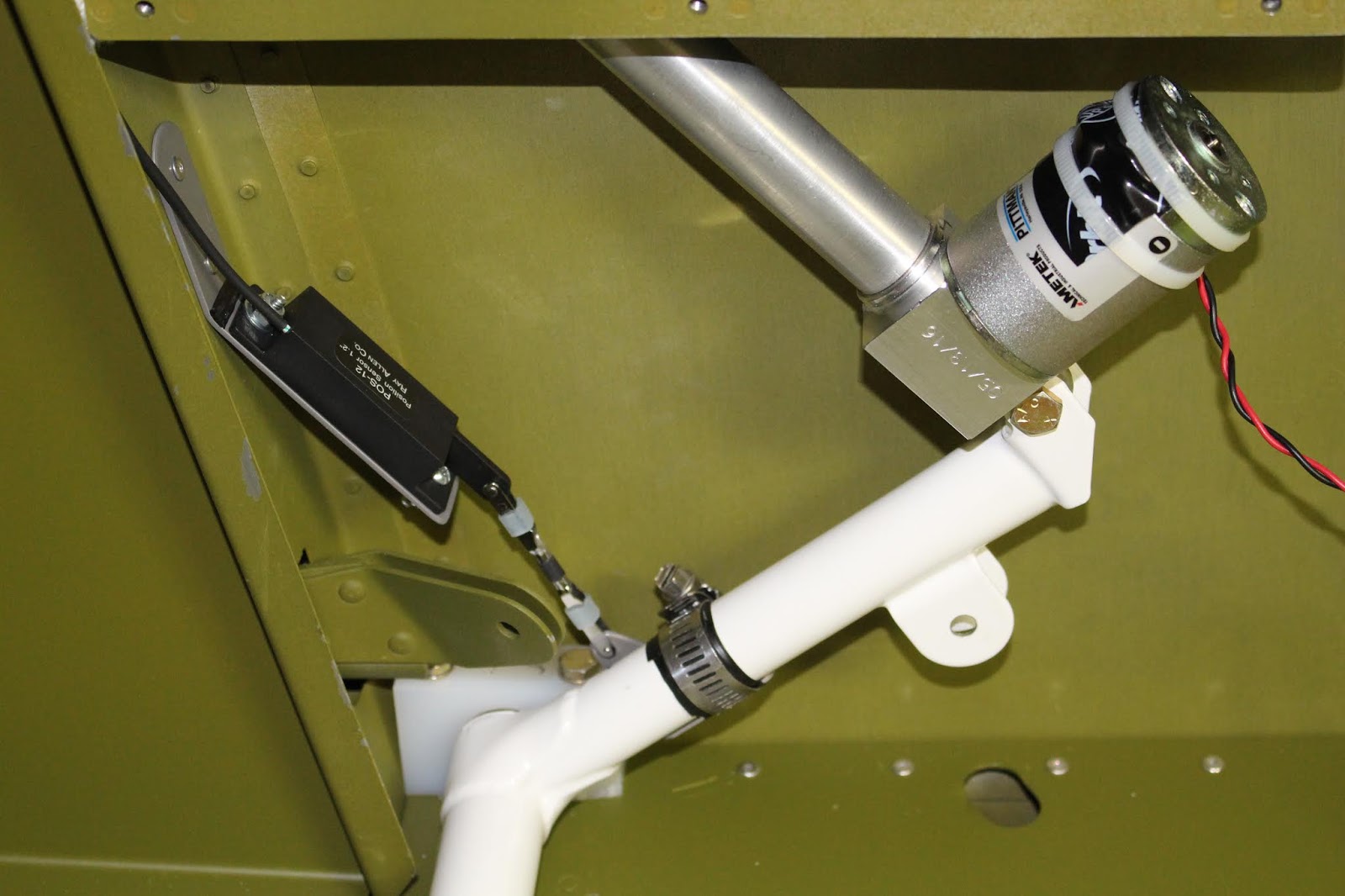
While waiting for the powdercoating I decided to tackle the flap position sensor setup. Since this is not addressed in the plans or instructions at all, I did some research on where and how other RV-8 builders have installed the POS-12 Position Sensor to use as a flap position sensor. Based on that information I began to fabricate brackets that would allow me to attach the flap sensor to the flap actuation weldment. I made a bracket that would attach the sensor to the adjacent bulkhead and angle the sensor in the correct direction for actuation. The sensor would mount to the bracket with 6-32 screws, washers and nuts set in opposite directions to address clearance issues. I determined the travel of the sensor arm (about 1.1 inches) and plotted the travel of the weldment arm on a piece of card stock. From this, I determined a range of locations that would cause the sensor arm to move its full distance or less when attached to the weldment. I also determined the optimal location for attaching the bulkhead bracket, shortened the bracket to fit better and drilled pilot holes for attaching the bracket to the bulkhead. Then it was prepped and painted. Clamping the bracket to the bulkhead, I determined the best location for mounting and match-drilled holes in the bulkhead; I planned to use blind rivets to attach it, but for testing it was clecoed in place. I obtained two clevises, some 4-40 threaded rod and nuts from a local hobby store and used them to fabricate linkage. The aft clevis would attach directly to the sensor arm. Initially planning to attach the forward clevis to the weldment with an Adel clamp and hardware, I fabricated a link that would attach to both. I did initial travel testing by taping the link to the weldment or using zip-ties, running the flap motor through the entire travel and seeing if the actuation was as desired, i.e. full travel (or close) without strain at either extreme. I didn't have the correct size Adel clamp in stock and didn't want to bother ordering one from Aircraft Spruce, but my local hardware store didn't stock the right size either. So I decided to fabricate another bracket that would attach directly to the weldment with a hose clamp and locate the forward clevis in the correct place. Once testing confirmed the viability of the new bracket, it was prepped and painted. I crimped molex connectors to the sensor wires before it was permanently installed. The bulkhead bracket was blind riveted in place, the sensor was tightened down and testing continued on the precise location of the weldment bracket and the length of the clevis link. The clevis link needed to be shortened slightly and the placement of the bracket refined. Thick PVC tape was put on the weldment to protect it from the hose clamp; additional electrical tape was wrapped around the bracket and weldment for more protection. After further refinement, the hose clamp was tightened and the assembly was tested successfully through the full range of motion.


 Some other side jobs were done during this period. In anticipation of the engine being mounted, I devised a method of attaching counterweights to the tail securely. I match-drilled some angle stock to bolt to the horizontal stabilizer attach bars and cut a length of pipe for the weights, notching the pipe to clear the bolt heads securing the angle stock and allowing the pipe to nest in the angle and be clamped in place with a hose clamp. I bought two 35 lb. barbell weights and plan to hang one on either end of the pipe. I'll probably run some all-thread through the pipe and retain the weights on the pipe with large washers and nuts. I'll have to figure out the best way to keep the weights away from the fuselage... maybe with pipe insulation or some sort of padding. Not sure about all this yet; it seems a bit lame, but it's not a permanent installation. It just needs to do a job. More on this later.


I also got around to mounting the com antenna to the belly and connecting it. After using the battery a lot to run the flap motor, I put it on the charger but it only needed a few minutes to regain full charge. The Odyssey battery retains its charge in storage very well. I attached the positive cable to the master solenoid, placed the battery adapter box into the battery tray, placed the battery in the box with the spacer block on top and secured the battery and spacer block with the tie-down bar. The battery will remain disconnected for now.


I want to be able to mount the canopy slide and rails permanently as soon as possible, so I will need to get the cockpit rails painted flat black and prime the slide mounting area. I've begun masking the fuselage in preparation for this. I don't think I'll have to erect the whole booth to get this done, but I will have to put the fans and door plug in place and probably a few sections of the side walls to direct the airflow and contain any overspray. Another big hassle for a small job... but I do want to get it done soon. I'll need to wait until the tailwheel spring is reinstalled and the tailwheel remounted, because I want to do the painting with the fuselage sitting on the tailwheel and I'll want to be able to maneuver the fuselage as needed.


That brings us up to the present. Speaking of the present, it's Christmas Eve. I'm tempted to wait till the end of the year to publish this, but with the holidays and many other distractions looming, I doubt I'll get much more done in 2018 aside from more masking. So that's it for this year; another very good year overall. I'm still hoping this airplane will make it to the hangar in 2019, and if I keep the distractions at bay and work on it every day, I think I can make it happen. Happy Holidays to us all, and as always... stay tuned.