Tuesday, June 30, 2015

Horizontal and Vertical Stabilizers Complete

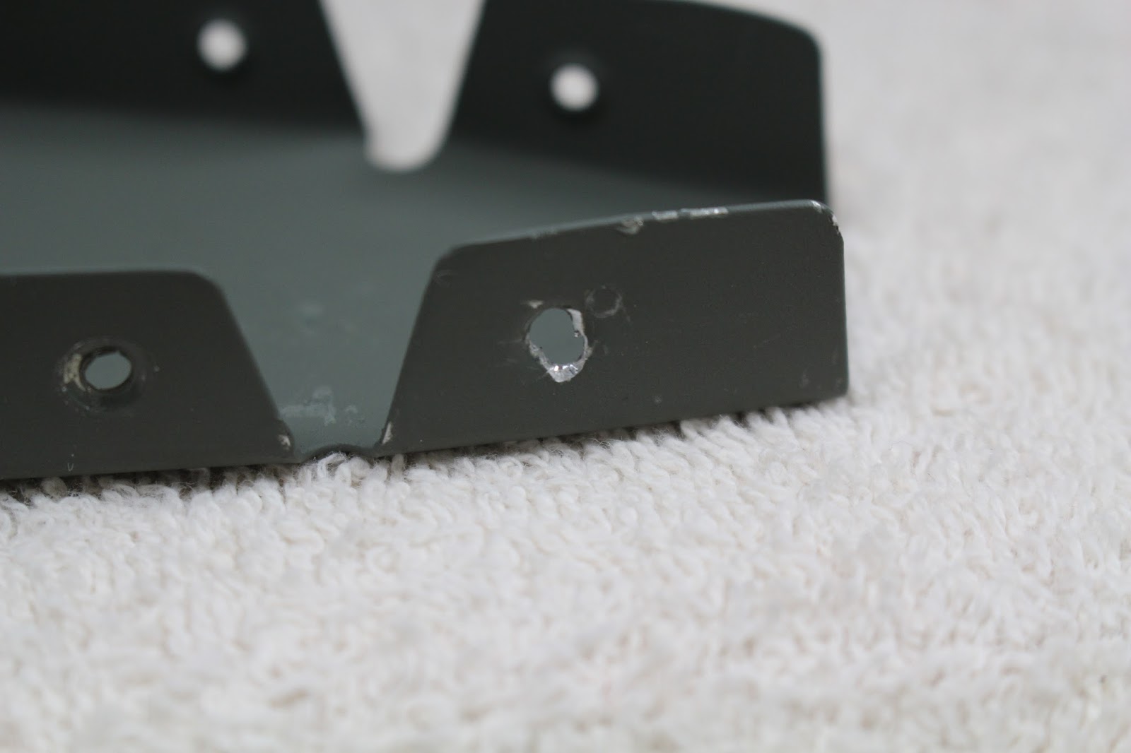
     After seeking some advice from the Vans Air Force forum about my errant dimple, I spoke with the factory, and they didn't seem to think it was a big deal... so I gently flattened and deburred the bad hole, dimpled the good one and continued building.  I did some research on fillers, and will probably use either aluminum body filler or ProSeal to repair the flaw.  No hurry on that decision.
     The next step was to start priming parts.  I stuck by my decision to leave alclad parts bare.
     I riveted the rear spar assembly together, and had to find a torque wrench calibrated in inch/lbs before I could tighten the bolts holding the rear bearing assembly to the rear spar.  My search turned up Performance Tool, an impressive tool store not far from my local Harbor Freight.  So I went to both stores and got two high-quality torque wrenches for my tool collection.  Riveting the front spar together was slightly trickier than I thought it would be... especially since I used a couple rivets of the wrong length.  Another lesson learned: double, triple and quadruple check your rivet specs.  I had to drill a few out, but the replacements turned out fine.
I added the inboard ribs next.  Tricky access; replaced a couple rivets.
I mocked up the skeleton one last time before working on riveting the skins.
     The first step in skinning the horizontal stabilizer is to rivet the middle nose ribs to the top of the skins.  It was possible to do this myself, but it would have demanded a very awkward reach with both the bucking bar and the rivet gun.  For the first time I decided that I wanted a helper to buck the rivets, so I enlisted the help of Mike Oswald.  Mike is a friend who used to own a recording studio, and we've worked on numerous sessions together.  He is also a former USAF powerplant mechanic, and although he never worked on airframes, I knew he would be an apt student.  We went over the basics of riveting, and assembled some test pieces I had fabricated for the occasion before starting work on my ribs and skins.  We started with the right side, and the first two rivets we chose went well.  The third rivet was the infamous front nose rivet; this is the one that is a problem for a lot of beginning builders because the skin is under tension, and it's hard to get the two pieces together tightly when setting the rivet.  On our first attempt, there was a slight gap between the rib flange and the skin, and I thought we should do better than that.  Drilling out the rivet created another mistake... as the factory head gave way, the skin tension popped the pieces apart.  The rivet shank was still firmly set in the rib flange, and when I tried to continue drilling it out, the bit slipped off the shank and contacted the rib.  I ended up having to drill out the other two rivets and removing the rib from the skin in order to remove the stuck rivet shank, and when I finally got it out of there I realized I had drilled another half-hole occlusion of the original hole.  
     The resulting oval was too large to fix by drilling out to #30 and using an "oops rivet".  Needless to say, I was a bit miffed.  We stopped working, went inside and did some research on the VAF site to see if there was any way of salvaging the part.  The skin hole was slightly enlarged but still usable... but I wasn't feeling good about that rib.  I decided to put off the decision, and we went ahead and attached the left center nose rib to the left skin top.  We figured out a way to preload the skin to keep it tight on the front rib flange, and this installation went well.  After more mock-ups with the skeleton in a couple configurations, we got the bottom blind rivets set for the left middle rib, and called it a day.  Of course this was a Saturday, so Vans was closed.  I eventually decided to replace the right nose rib.  This meant waiting for delivery and doing the additional prep work and priming, but it was worth the peace of mind.  That front rivet is a critical one; I didn't want it compromised.
     In the meantime, I went ahead and finished skinning the left side, which went smoothly.  I learned how to buck the small rivets along the front spar by feel, pressing the flat side of the bucking bar against the shop head with just two fingertips.  There were a few that I needed to touch up, but no mistakes or drill-outs.
     I chose Priority Mail for the delivery of the replacement nose rib, and it arrived very quickly.  After prepping and priming, I called Mike up and got it safely installed on the right skin, top and bottom.  Note in the photo, there is a missing blind rivet on the bottom; I caught that and installed it later.
     I continued with the right skin installation, and only had one other minor issue.  After clecoing the skin to the front spar and ribs and riveting the skin to the front spar, I set the blind rivets that join the middle ribs to the front spar.  This is tight access for the blind rivet puller, and you have to determine proper seating of the rivet by touch as best as possible.  I set the center of the three pulled rivets, and it felt fine... but after setting the other two, the center blind rivet was sitting just a bit proud.  This might have been caused by my removing all the clecos from those three parts before pulling the center rivet.  The top and bottom rivets are very good, and although the center one's factory head is just a hair off the center rib flange, it's very tight; there's no movement in the rivet... and there's no way I was going to try and replace it with the skin already riveted to the front spar.  I made a mental note to discuss it with a Tech Counselor on my first inspection.
     I continued installing the right skin.  One aspect of this that somewhat complicated the process was that I needed to flip the part several times as I worked.  I didn't want to take any chances on twisting or bending the front spar assembly, so I had to cleco the rear spar in place every time I wanted to move the part... including every other hole along the top & bottom skins.  I had to do that three or four times before I got all the rivets set for the right skin.
     At this point, it was time to schedule my first Tech Counselor visit.  Although not a FAA prerequisite,  as a first time builder I was wisely advised to have an EAA Tech Counselor inspect my work before I riveted the rear spar in place and closed up my horizontal stabilizer permanently.  I did some research and found three candidates in the area, two of which were fellow members of EAA Chapter 113.  Daniel Jones keeps his RV-9 in the chapter's hangar, and is the recommended Tech Counselor for Van's RV projects.  He contacted me and we scheduled a visit for the following Saturday.  
     I had a few days to wait, so I set the horizontal stabilizer aside and got busy on the vertical stabilizer.  I clecoed the skeleton together and match-drilled all spar and rib holes, disassembled the parts and fluted, straghtened and deburred the ribs.  I clecoed the skin on, match-drilled the skin holes and finished deburring all parts.  Then came another disassembly, dimpling the skins, spars and ribs, and countersinking the spar doubler.  I prepped and primed all non-alclad parts and set them aside to prepare for the Tech Counselor visit.
     Dan's visit was friendly and informative.  He had a lot of good things to say about the work I had done and how I approached the project.  He did give several helpful suggestions about riveting and deburring.  In general my rivets looked good, but I was just on the edge of undersize on some of my shop heads.  I told him I had thought underdriving was better than overdriving, and he agreed... but ideally the rivet gauge should just barely fit over the shop head.  I was making sure the gauge had no play around the rivet, but I learned it's better to overdrive very slightly than underdrive a shop head.  I have since adjusted my technique accordingly for both the rivet gun and the squeezer.  I asked him about that slightly proud blind rivet on the right side, and he agreed it's best to leave it as is.  He also gave some good pointers on deburring, and we discussed it at length.  The fingernail test is the best test for a sheet metal edge: if your fingernail detects the slightest burr, work the part just a bit more.  He recommended getting some jeweler's files and some special Dremel pads for working the tight corners, and did a good job of explaining potential causes for stress cracks.  We also talked about painting, and I explained my stance on not painting alclad parts.  He understood... but he suggested that the exposed ribs and spars on the empennage would have been better off being primed, especially since I'm planning to paint the exterior of my aircraft.  There is also the issue that corrosion usually begins where two parts meet.  After our discussion, I think I'm going back to my first plan of priming all ribs, spars and stiffeners, and not priming the interior alclad skin surfaces of the closed parts.
     He spent a little over an hour here, and I think we both could have continued our conversation much longer than that.  He gave me a written inspection report, and insisted that there was no charge for the inspection.  In fact, he even refused my offer of gas money for the trip out to my house.  Instead, he offered to take me up in his RV-9; I could help share the cost of fuel, and he could spend some time with me going over the details of his airplane and his building experience.  All I can say is, I can't wait!
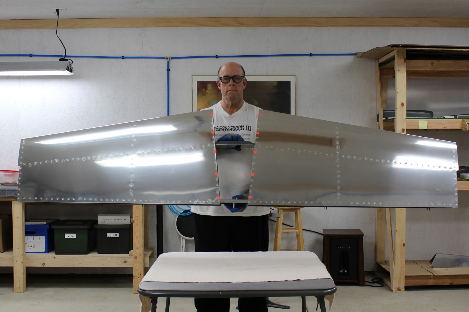
     The next day I got an early start.  I unbolted the center hinge bearing assembly from the rear HS spar assembly prepped and primed the exterior side.  While it was drying, I prepped and painted the remaining VS ribs and spars.  Then I was able to insert the HS rear spar, cleco it and rivet it into place.  I bolted the center hinge bearing assembly back in place, torqued it to the proper specs... and with that, my horizontal stabilizer was complete.  I laid two foam cushions and a drop cloth on one of my folding tables, placed the assembly on the cushions and covered it for storage.
     There was still time left in the day, and I was still motivated, so I got back to work on the vertical stabilizer.  I riveted the spar doubler and hinge brackets to the rear spar, completing that assembly.  The paint was dry enough to handle, but not completely cured, and working with it was dicey.  I had a couple of rivets that needed to be fixed, but that went well.  Before I left the shop for the day, I checked out the front spar primer, and resprayed some flaws in the finish.
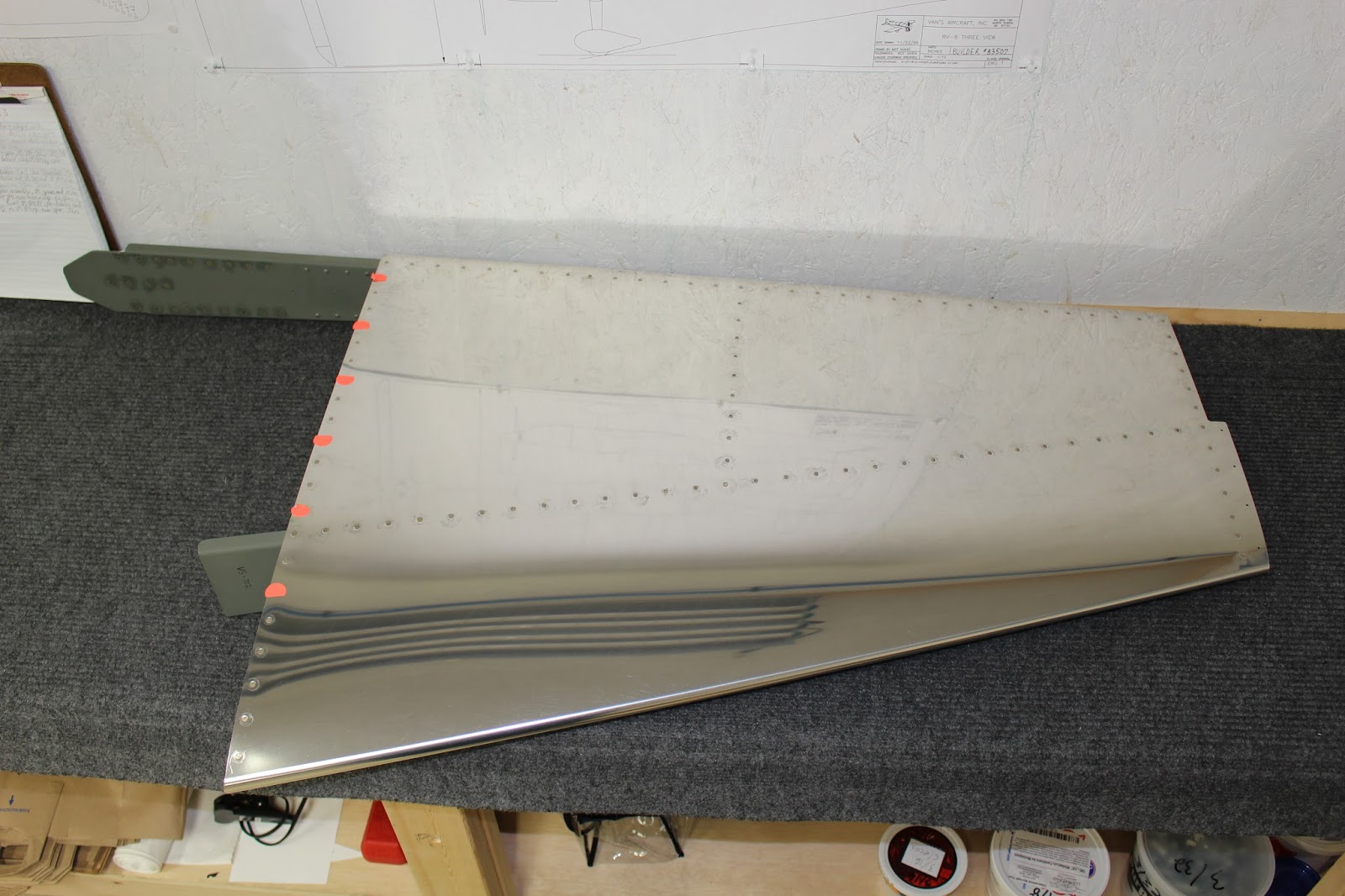
     That Sunday had been a long and momentous day, and I initially planned to take a break from the airplane for a short period.  But the next day, I was still inspired... so I finished the vertical stabilizer in one day.  Riveting the ribs to the front spar was a little trickier than I expected, and I had to drill out one badly dinged rivet that I didn't discover until after the skin was on.  I also made the classic mistake of neglecting to leave out some of the lower rib rivets for later fairing attachment, but I caught it early and only had to remove two out of twelve.  Squeezing the rear spar/skin rivets was also trickier than expected, because of clearance issues caused by the spar doubler rivets and hinge brackets.  I had to buck the skin rivets by two of the hinge brackets with the footed bucking bar, because the squeezer just couldn't get all the way in for a clean squeeze.  But I got it all done.

     So I made two milestones in as many days.  I shared all the progress on Facebook and got a surprising amount of interest.  I put the vertical stabilizer in storage, and I think that will be it for working on the airplane for a little while.  I did get my clothing made, although that took longer than expected, and wasn't without its share of problems.  Since I used the VAF logo in my designs, I followed their usage guidelines and made charitable donations to the Warbirds of Glory Museum's Sandbar Mitchell Restoration fund and the CAF's kickstarter program for the restoration of the C-47 "That's All, Brother" that led the D-Day invasion.  
     The last thing I had to do was get caught up on this blog.  Now that's done, and I can focus on all the work I need to do for AirVenture.  I am really looking forward to this year, even more so than previous years, because it will be my first year as an actual airplane builder, and I'm looking forward to meeting many of the new aviation friends I've made recently.  My event social calendar is filling up.... the two-day SportAir Van's RV Builders Workshop; other workshops and seminars; the VAF Social; The Van's Banquet; the EAA Chapter 113 gathering; meeting Kermit Weeks and looking for many other flying acquaintances that may be attending.  It will be wonderful staying in the Hilton Garden Inn during the first two nights, and getting an early bird's selection for my Camp Scholler site.  Even the trip there will be special, because I'm taking the S.S. Badger ferry from Ludington to Manitowoc.  So much more pleasant and fun than driving around Lake Michigan and through Chicago... I'm really looking forward to it.
     I even managed to finish this blog the day before July 1st, so as a monthly blog, I'm staying right on schedule.  It sure does make for long entries, though... but I still think it's all worth the effort.  I hope you do, too.

Tuesday, June 2, 2015

My First Major Mistake

     The day I have dreaded has arrived.  Ths morning I made my first major mistake on an aircraft part.  I've read accounts of other builders making this same mistake, and swore it wouldn't happen to me... I even devised a strategy to avoid it.  But my strategy failed.
     I had finished deburring all the horizontal stabilizer parts, and was beginning to dimple the skins.  I thought I'd start with the hard parts.  I wanted to see how many of the center rib leading edge holes I could dimple with the C-frame table before I had to resort to using the rivet puller and close-quarters set.  Other builders had made the mistake of punching unwanted holes when the dimple die came astray of the rivet hole.  I thought I'd avoid that mistake by carefully locating the male die into the hole, then pre-loading the female die to sandwich the piece firmly in place before striking with the mallet.  Well... it came astray anyway... and I ended up with a punched and dimpled hole just adjacent to the one that should have been dimpled.
     Fortunately, this happened on the bottom of the skin, so whatever corrective measures I make won't be glaringly obvious to the appearance of the aircraft.  As I see it, I have several choices:
1. I flatten the errant dimple, dimple and rivet the correct hole and leave the error as is... or perhaps fill it with bondo, liquid metal or welding before painting.
2. I leave the errant dimple, dimple the correct hole, drill a corresponding errant hole in the rib, and rivet both holes.
3. Order a new skin, re-drill, deburr and hope the holes match the ribs and spars.
     My biggest concern is the proximity of the holes.  They're very close together, and I'm sure that complicates the situation.  I'm going to do some research online first to see if other builders' errors were similar to mine and what corrective measures they took before deciding on my own plan of action.
     Damn.  Well, I knew it was coming... and I'm sure there will be more mistakes in my future.  Build and learn.

Sunday, May 31, 2015

May Progress

     I like the title of this post.  Like plans and instructions, it can be interpreted in so many ways...
     Actual work on the empennage began on May 19, when I removed the vinyl all the covered alclad parts except the outside of the skins.  Whether or not to remove the vinyl is only one of the many aspects of building a Vans aircraft that is subject to debate among builders.  I based my decision to remove the vinyl on several factors.  First, Vans recommends removing the vinyl as soon as practical, because the vinyl glue can become more difficult to remove as it gets older, and it can also trap moisture that can start corrosion.  Since I will be painting my aircraft flat olive drab and neutral grey and want to replicate the rough-and-ready look of a mid-war fighter that is being rushed off a production line, I'm not worried about tiny scratches on the skins or other alclad parts.  I keep my carpeted work surfaces as clean as possible, and wear gloves while handling parts to minimize fingerprints and smudges.  I'm leaving the exterior skin vinyl on to protect it while the skins are nested in storage and handled during match drilling, and removing it just before deburring and dimpling.
     Perhaps the biggest subject of debate has been priming and painting... even to the point that Vans has a running gag on their phone system about it.  While waiting on hold for builder support, I heard one of the automated voices say "We apologize for the delay; Vans is currently working on negotiating a truce in the primer wars", which made me laugh.  After giving this a lot of thought and research, including reading all of Vans recommendations and discussing it with their builder support and other RV builders, I've decided that I will only prime non-alcad interior parts.  Exterior parts will receive the proper primer and topcoat.  Given the expected use this aircraft will see, and the fact that I intend to always keep it hangared in a non-salt-air environment, I do not expect to have any corrosion problems during my lifetime.
     I started work on the horizontal stabilizer rear spar assembly, and completed most of the initial work in one day.  I discovered that I was missing two elevator hinge brackets, so I ordered them from Vans.  This should have been a no-cost item, but I paid extra shipping to expedite delivery as this was discovered right before the long Memorial Day weekend. 
     I painted the aluminum flange of the center bearing before assembling the bearing bracket.  I applied metal-etching primer and a top coat of flat camo green.
This was the very first rivet I drove on my aircraft... a momentous occasion.
     The plans call for using AN470AD4-5 length rivets on this assembly.  My first couple rivets seemed fine, but the shop head was very slightly undersized in diameter.  It was obvious that I'd have to overdrive the rivets to get them to fit the rivet gauge, and I didn't want to do that.  Later, I checked other builders websites, and learned that some builders used -6 rivets in this location.  I made a note to check with Vans about this later.  I drove all six rivets with the assembly clecoed to the rear spar; it seemed a better idea than trying to clamp it elsewhere.  I laid down towels to protect the spar from nicks from the gun or bucking bar.  There was one rivet I wasn't happy with; overdriven with a significant smilie on the manufactured head, so I drilled it out and drove another which looked much better.
     My next step was making templates for bending the 6 degree angle into the reinforcement angle, splice angle and front spar tabs; the spar doublers are manufactured with this bend in place.  I made one out of heavy paper stock, and another out of scrap aluminum. 
     I drilled the first batch of holes in the front spar tabs, doublers and angles.  I laid out and cut the tapers on the ends of the angles in stages using a hacksaw, grinding wheel, vixen file and scotchbrite wheel to sculpt the final shape.


     I got the 6 degree bends dialed in on the angle pieces, but held off bending the front spar tabs because I suspected some clearance problems.  If I had drilled and cut the relief holes on the spar tabs as they were shown on the blueprints, they would have come much too close to some of the rivet holes.  At this point, I figured I had enough questions to warrant my first call to Vans Builder Support.  I asked about the rivet size for the center bearing bracket assembly, and they said the rivets I set should be fine.  The adviser put my mind at ease with his relaxed attitude, reminding me that this wasn't microsurgery; I'm building airplane parts.  Measurements need not be made down to the thousandths (at least not in this instance); reasonable tolerances are to be expected.  That was good news to me, because I could sense that I may have been heading down the road to OCD with this project, and it would be unrealistic to expect perfection with the skill set I have now.  This is an educational project; it is under that premise that experimental aircraft are even allowed to exist. I asked about the front spar tab relief notch, and how the blueprint design would impinge on the nearest rivet hole.  Again, he said the notch didn't need to look exactly like the blueprint, and in any case it probably shouldn't be any deeper than the relief milled into the spar doubler, which is much shallower than the blueprint notch.  Creating the notch with a circular file and smoothing the corners and edges would be just fine.  Same with trimming the front spar flanges to clear the inboard rib; the blueprints didn't specify the angle of the trim, or any specific measurements.  The advisor said just make sure it clears, and isn't too close to the nearest flange/skin rivet hole... more on that later.
     My last question was about the aircraft serial number.  I had tried to determine what mine would be, and even after doing research through the VAF site and others, I hadn't drawn any firm conclusions.  I was told that, as the builder of the aircraft, I could assign any aircraft serial number I wanted to use, but it was common practice for most Vans aircraft builder to use their builder's number as they are specific to each individual aircraft, rather than the person doing the building.  I also learned that the first one or two numbers designate the model of Vans RV aircraft (3, 4, 6, 7, 8, 9, 10, 12, 14) and the following numbers are the builder number of that model.  So in my case, 83507 indicates that I am builder #3507 of the RV-8 model.  Works for me; that will be my serial number.
     I also went to the FAA's website and reserved my tail number.  My goal was to create an N number that held significance to me, but more importantly it had to be something easy to read back on the radio; something that would roll off my clumsy tongue.  I wrote down some possibilities, and found a few available numbers that would fit the bill, so I reserved one.  And of course now that I had that piece of the puzzle, I went back into all my previous RV-8 artwork featuring my current paint scheme, and added the correct N-number to each drawing.  I also designed VAF and RV-8 logos that I will use on custom T-shirts, polo shirts, coveralls and flight suits.  Now that I'm officially in the club, I want to look the part.
This logo is for T-shirts and the back of coveralls and flight suits:

This logo is for the name badge on coveralls and flight suits:

This is the polo shirt logo:
     Back to building.  I notched the front spar tabs and bent them to the required angle.  Now the spars, doublers and angles all fit together properly.  As for the spar flange trimming, the blueprint drawing showed an angle that worked out to be about 19 degrees.  I chose an even 20 degrees as a starting poing, cut them with shears and smoothed the edges.  As building progressed, I realized they needed additioal relief to clear the front flanges of the inboard ribs, but I wouldn't know how much until I did a test-fit with the skins on.  I didn't know it then, but I was making things rather difficult for myself with this plan.  Meanwhile, the missing hinge brackets arrived, so I match-drilled them.  I fluted and deburred the ribs for both sides, and assembled the left skeleton to test-fit the skin.
     Getting the skin in place was a little more awkward than expected, and created some scratches on the inside of the skin around the front of the ribs.  But I adjusted my personal "be careful, you clumsy idiot" setting to a higher level, and soon it was clecoed nicely in place.  Test fitting the left inboard rib confirmed that more relief was needed on the front spar flanges... so that meant removing most of the skin clecos and carefully pulling the front spar away from the skin and ribs.  Some work with a dremel tool and the scotchbrite wheel on both the front spars and the front rib flange notches, and I had the clearance I needed... and now I also knew where the inboard rib needed to fit on the front spar, so I could do the work on the right spar before I test-fit that skin.
     The instructions say to do all the test-fitting on the left horizontal stabilizer and duplicate the process on the right one, but I ended up doing both somewhat concurrently.  As a result, I had to be careful not to miss a step... but I was working slowly and methodically, double-checking myself often, so nothing was forgotten.  Some of the spar holes can't be drilled until this stage, and some of the access is tight.  The Cleaveland Tools RV builder's toolkit didn't include an angle drill, and it looked like I might need one at this stage.  Harbor Freight didn't have one that was small enough, so I ordered an angle drill adaptor kit from Cleaveland Tool, along with a footed bucking bar.  As I continued working, I realized I could access the difficult spar holes using the long flexible bits that come with the original toolkit, so I used those to drill the initial holes to #40.  Once the inboard rib fitting was complete, I match-drilled all the skin holes to the ribs and spars on both sides.
     I removed the skins, assembled both skeletons and finished a few remaining spar holes.  The plans never mentioned having to drill the difficult spar holes out to #30, but I knew it was necessary based on the rivet call-out.  Nevertheless, I called and checked with Vans before resizing them, because it's easy to make a hole larger, but very difficult to make one smaller.  I wanted to make sure I was doing it right.  That was when I discussed the Primer Wars with the advisor, and made the decision to only prime the non-alclad parts with a light coat of metal-etching primer.  With all the drilling done, I disassembled everything in preparation for deburring and dimpling, which I will start tomorrow... June 1... after I pay the monthly bills, of course.
     So ends the eventful month of May.  I keep reminding myself that I have the luxury of time on my side.  Since I won't be able to order the wings and fuselage quickbuild kits for at least seven months to a year, I can move as slowly and carefully as I wish on this part of the project, which reduces the risk of making making the kind of mistakes that can happen from doing something before I'm ready.  I still have the SportAir Workshop and all of AirVenture to come... and that trip is getting closer.  The details of my itinerary are coming together and will include the VAF gathering Monday night, which should be especially fun.  I'm working on getting the custom shirts and overalls made, and will post photos when they are done.  Now that I have serial and registration numbers, I will pursue builder's insurance... and that may allow me to start a hangar lease at PTK.  Speaking of which, I am flying twice a month now with the instructors at DCT Aviation, in Warriors and Archers when the weather is good, and in simulators when it isn't.  The weight loss still continues; I'm down almost 40 pounds so far.  That's almost halfway to my goal weight, which is very encouraging.  As for this blog, I'm beginning to think I may make monthly entries here, since I've been doing the KitLog Pro entries daily.  I will play that by ear; after all, I'm used to that.  I've been playing songs by ear for fifty years now.  Hope I can say that about flying someday.. or at least come close.

Sunday, May 17, 2015

Empennage in Possession

     While waiting for the empennage to arrive, I took down the paint booth, cleaned and reorganized the wood shop and made some modifications to the C-frame table to increase its tool-holding utility. I added short sidewalls along the 2x4 side braces, which hold my electric drill box and the Dremel tool box perfectly.  I also built in a holster for the rivet gun and air drill on one side.  I'm happy with the result.
     At 3:30pm Friday May 15, 2015, FedEx delivered my two empennage boxes in good condition.  I spent a few hours doing inventory; everything was there.  The game is afoot!
     The next day I organized the parts into four main groups: rudder, elevator, horizontal stabilizer and vertical stabilizer.  I also went through all the small bagged parts and sorted all the rivets into my existing containers.  As long as I was organizing, I built a dedicated rivet container shelf and added it to the front of my large shelf unit.  I suppose it wasn't really necessary... but I like to get as organized as possible before I start working.  Now all the parts are centrally located and categorized.
     I also made my first construction log entry in my KitLog Pro program... and ran into some difficulties.  After taking advantage of the freeware trial period a few months ago, I purchased the program.  Now I get an error message on startup, but it gives me the option of continuing.  I had trouble figuring out how to upload photos into the construction log, so I clicked on help... but help wasn't available.  To make a long story short, I figured out how to upload photos into the constuction log, and although help still isn't available, I'll manage without it.  I also uploaded my construction log to MyKitLog.com; it can be viewed at http://www.mykitlog.com/goatflieg.  So now I've got two building blogs to manage... but that's ok.  I'd rather have too many resources available to me than too few.
     I've been mulling over ideas for a blueprint table.  I had originally planned to build something similar to what Joe Schumacher made for his parts & blueprints on the TV show From The Ground Up.  But that would mean waiting until I have the wood from the wing & fuselage cases, which won't be here for another year at least.  I have a tall easel I built to use as a rudiment chart for my drum students, but I'm not currently teaching lessons at my house.  So I brought the easel over to the shop and modified it to hold blueprints.  Again, overkill... but I like working out these little details.  Then I thought of using one of my music stands to hold the assembly instructions.  That would have worked ok... but when I was taking photos and looking at the easel, I got a great idea.  Since the original easel went much lower than the area I needed for blueprints, I could add a folding bookstand to the easel.  I could build it at the perfect height and angle for reading the plans and examining the blueprints while standing upright, and it would fold up for easy storage.  I had most of the material on hand; I just had to buy some square wood stock to use as a paper shelf, and the cleat for the table support.  It came together very quickly... and I'm thrilled with the results.  It will serve its purpose perfectly!

     My next task is to study the pre-plans thoroughly, and review other builder's blogs.  I've had the current pre-plans for two years... and the previous edition for almost fifteen years.  But it was hard to get into them when the actual building was still a far-away dream.  Now the time has come; it's no longer a dream.  The preparation and practice kits are done.  I actually own some of the parts of my own aircraft, and they await my labors.  I want to do everything I can to make sure I do this as well as I can, and see this project completed and flying.
     To be continued... of course.