After all the prep work was complete, it was time to take a big breath and try to get my head back into the building game. I started by reviewing the wing plans and instructions, trying my best to review the construction sequence, determine my starting point on the partially assembled wings and make sure I wasn't missing any previous steps. I must admit it was difficult to get my brain in gear after such a long layoff from actual construction. It took a few false steps for me to realize that I needed to review the introductory construction documents so that everything wouldn't seem so nebulous and uncertain. It's well known that once you've built the empennage, Van's assumes you begin to understand what needs to be done in general terms, and backs off somewhat from giving detailed step-by-step instructions. I heard a great analogy of this situation recently, comparing Van's aircraft construction to food preparation. With the empennage, you get a complete recipe with the ingredients and quantities precisely determined and detailed cooking instructions. Working on the wings, you're given a general recipe and ingredient list, but no quantities or instructions. Finishing the fuselage, you're told to make a casserole. With the finishing kit and firewall forward, you're reminded that you'll need to eat something. This is an exaggeration, of course... but the further you get into this project, the more details you'll have to figure out for yourself. In reviewing for this entry, two things became obvious to me. One: without instructional hand-holding, I tend to skip around from task to task and work on different steps simultaneously, but that can serve the good purpose of keeping the bigger picture in mind so I don't accidentally build myself into some unconsidered corner. And B: although I wasn't putting in the eight-hour days I thought I would, I have followed the advice of doing something every day... even if some days are only spent on planning and other preliminary tasks. As a result, I really did get a lot done this month. For an accurate timeline on the sequence of events, you'll want to refer to my kitlog site. Here, I'll just describe the various types of work required and how I addressed them.
My first step on the wings was to assemble the aileron brackets. This seemed simple enough... but I was reminded that I should examine the plans carefully to make sure I completely understood all aspects of assembly and proper sequence of steps, because the instructions weren't going to remind me. For example, I prepped the parts and primed them... and realized that I hadn't checked the rivet call-outs which included some unexpected flush rivets. So I had to countersink parts after painting them and touch them up later. Also, the brackets had to be used as templates for drilling rivet holes in the end wing rib, so making sure I had the assembly sequence planned correctly was important. Most rivets could be squeezed, but a few had to be bucked, and I had to redo a couple botched rivets until I regained my skills with a rivet gun.


Now to work on the aileron fairings and flap braces... and another gotcha. The aileron fairings were fairly straightforward, but the flap braces required some trimming to fit around the rear spar reinforcement fork, so I did that first. Then I clecoed all the fairings and braces into place to test fit. I knew that both of these attached to skins; the aileron fairings attach to the top skins and the flap braces attach to the bottom skins, so they require flush rivets. During the dimpling process, I didn't think far enough ahead (did I mention it took my head awhile to get back into the game?) and after dimpling both the braces and fairings, I realized that the flap hinges were supposed to sandwich the the flange of the flap brace between the bottom skin and the hinge tab... so I should have countersunk the flange instead of dimpling it. This was a lesson that I learned the hard way when I built my elevator trim tab; apparently the lesson was so hard I repressed it. I did some research on other builders' sites and because the instructions don't discuss the actual hinge installation, the assembly is treated in different ways. Some builders sandwiched the hinge tab between the skin and flap brace flange; I didn't want to do that because with the hinge already installed on the QB flaps, the skins wouldn't have aligned, and the drawing of the assembly on the plans is pretty clear about the placement of the skin, brace flange and hinge tab. Dimpling the hinge tab seemed to be a very bad idea; the softer aluminum would distort, shifting the eyelets around and making insertion of the long hinge pins a nightmare. The hinge tab needed to be match drilled and mated to a flat surface... another gotcha, since I had dimpled everything in advance (Hello? Brain? WAKE UP!). So I was facing the prospect of grinding and filing down the back side of all the dimples I did in both flap braces. A sizeable pain in the ass I managed to create for myself... but life is for learning... and an airplane kit is a stern teacher. I built another jig to hold the flap braces securely in place, clamped it to my riveting table and got to work grinding each dimple down individually, then smoothing the surface with files until flat. It took a while, but it was worth the effort. Once I was certain the parts were ready, I got them prepped and primed and riveted them to the rear spar. The instructions only mentioned riveting them to the rear spar; never mentioned the skin rivets. I knew that made sense with the flap braces, because that riveting incorporated the flap hinge assembly that they didn't address in detail. It didn't seem to me that anything was preventing me from riveting the aileron fairing to the skin; nothing else is incorporated into that assembly. But at this point I was feeling pretty gun shy and called Tech Support to make sure, and got their blessing.


I got the dimpling done on the bottom skins and ribs, attached the mounting brackets to the ailerons and started work on the aileron pushrods. I followed the tip I got from Joe Schumacher in the From The Ground Up video series and made templates for rivet hole placement. I also made a jig to hold the smaller-diameter pushrods straight during the drilling process. The larger bellcrank-to-stick tubes use six blind rivets; the smaller bellcrank-to-aileron tubes use long domed rivets that fit through the assemblies; riveting went smoothly for all.


Then I started work on fitting the bellcrank assemblies. During test fitting, I was surprised to find that I was unable to install the bellcranks without removing the mounting tabs that had been installed by the quickbuild crew because of clearance issues caused by the main spar flanges. I also discovered that the bellcranks tended to bind on their brass bushings, even after surface prep and sufficient lubrication. Reviewing VAF posts indicated that it was a common problem. The instructions called for reaming out the inside of the bushing for better fit of the attachment bolt... but the bellcrank is supposed to rotate around the bushing; the bushing is not supposed to rotate around the bolt. The binding symptoms were a bit odd. Something wasn't straight, but I couldn't tell if the problem was with the bushing or the bellcrank. So I decided to take the pieces to a local machinist to have it properly diagnosed. Larry Wiltfang of DFE Precision Engineering confirmed that all the parts had some issues. The bellcranks are known to develop distortions where the tabs are welded to the main pivot tube, and the bushings are mass produced to low tolerances and therefore not perfectly straight. Some light machining put everything right, and Larry also recommended a superior grease for the bushings: Kluber Isoflex NB 52. Not easy to find, and not cheap... but waterproof, lighter than most grease, and will outlast any other lubricant for this application. Another problem solved.


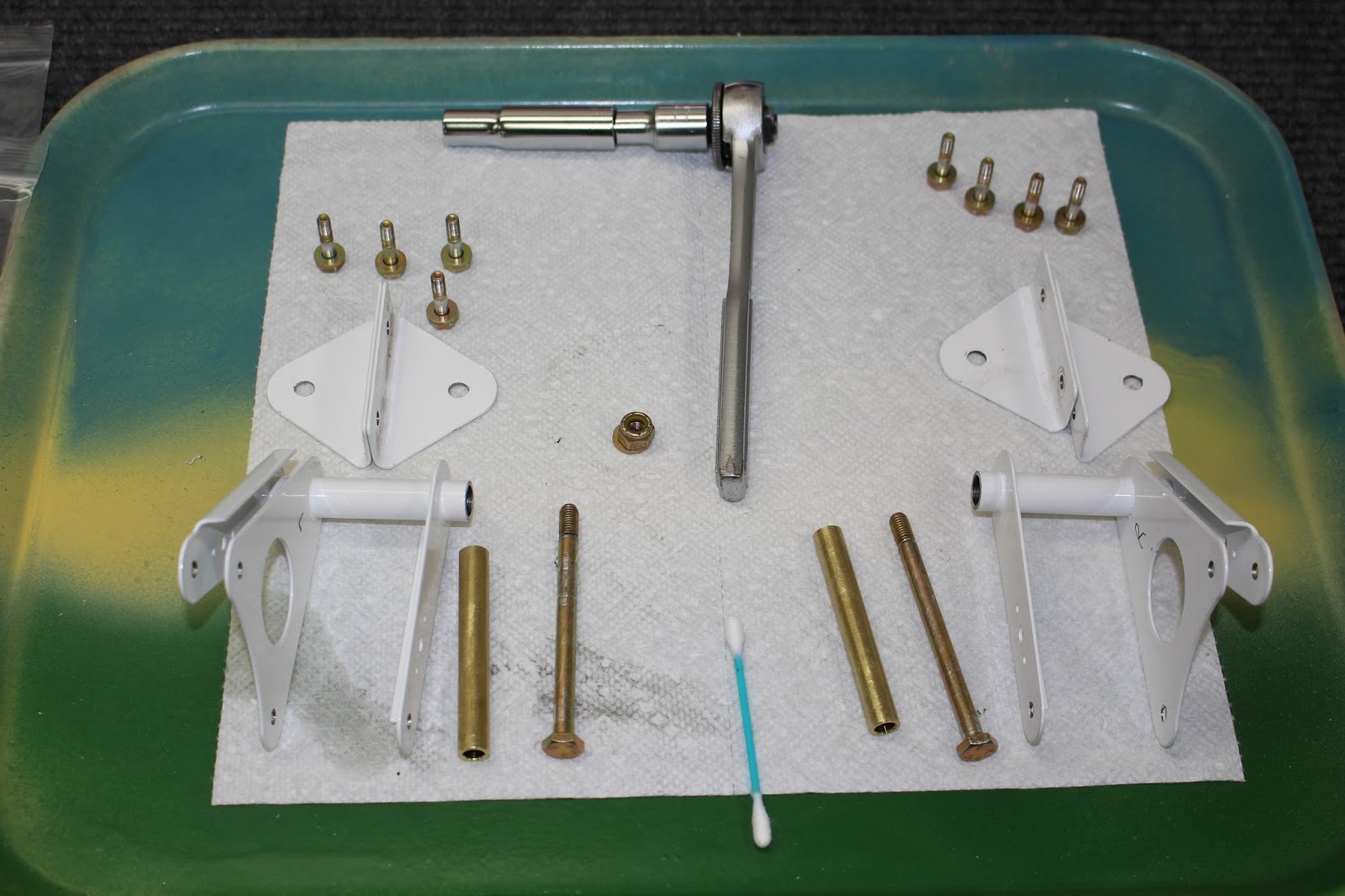

It would be awhile before I was able to refit the assembled bellcranks and adjust the pushrods because I had to order the special mounting tab that would incorporate the Garmin roll servo installation. In the meantime, I cut the bolt spacers for the ailerons and bellcranks and got them prepped and primed. To prepare for aileron alignment and bellcrank pushtube adjustment, I built a jig from angle iron specified in the plans that would bolt to the tooling holes in the end ribs. The ailerons are aligned in trail by extending the centerline of those tooling holes along the jig and making sure the trailing edge of each aileron lines up with the extended centerline on the jig. I also made a V-shaped cleat out of wood that bolts to the jig and holds the aileron securely in alignment. I originally drilled two sets of holes in the angle iron, thinking one set would be for the left aileron and one for the right. But it turned out to be easier to just use the same holes and use the jig upside down, with an extra hole in the cleat so it could be used for left and right ailerons.


Once I had the aftermarket bracket that would hold the right bellcrank and Garmin servo, I got the bellcrank brackets installed and torqued into place, marking bolts and nuts with torque paint. I installed the pushrods and using my aileron jig and the bellcrank jig supplied by Van's, I adjusted the pushrods to proper length and tightened the cinch nuts. Checking the travel gave me indications that I might need to relieve the pass-through holes in the rear spar for more clearance around the pushrods. I'll double-check and make any other adjustments before I close up the wing.

With the ailerons temporarily in place, I could start working on getting the flap hinges installed on the wing. The quickbuild wings come with the ailerons and flaps already assembled, and the flaps have their piano hinge halves riveted in place. It was my job to make sure I anchored the wing half of the hinge in the correct place so that I had a 1/4" space between the aileron and the flap with the trailing edges of both in alignment. Extra hinge stock is provided in the kit that needs to be measured and cut to the right length. Starting with the left flap hinge, I drew a centerline along the hinge tab for optimal rivet line placement; actual rivet hole locations would be determined by positioning the aileron and flap in trail and in alignment, using the pre-drilled holes in the wing skin and flap brace to mark potential rivet hole placement. Then I removed the hinge to see where the rivet hole marks were in relation to the centerline; they were reasonably close. There are a lot of different ways to maintain the critical spacing and alignment, which may explain why the instructions don't really discuss it.... you have to study the plans, study the parts, think about what needs to be done, and figure out how to do it. Again, it would have been easier for me to do this step if I already hadn't dimpled the skins and flap braces... but I figured out what I'd need to do. I found some cardboard that was exactly 1/4" thick and cut into a shape that I could use as a spacer between the aileron and the flap and taped it to the aileron. That made it easy to keep that spacing consistent. To begin affixing the hinge to the wing, I drilled the first rivet hole in the hinge at the aileron edge and clecoed it together. Using cleco clamps to pinch the parts together and maintain my desired alignment, I drilled every ninth hole and put in a cleco, checking my alignment as I continued along the length of the hinge toward the wing root. When the hinge was where I wanted it, I carefully marked all the rivet holes, removed the hinge half and mounted it to a piece of scrap wood. Being as accurate as possible, I used the spring punch to set drill marks, spun the long #40 drill by hand in each one to start the holes, then drilled and deburred them. Assembling the hinge halves together on the flap with the long hinge pin, I aligned the flap to the wing and clecoed the hinge to the wing skin and flap brace to check my work. Alignment was good, flap movement was smooth and the hinge pin wasn't binding. Success! Now it was time to do the same thing for the right flap. I did that hinge slightly differently... instead of the meticulous mark-punch-spin-drill method I used for the left side, I thought I might be more efficient and get even better alignment if I got the hinge half secured in place and hand spun the drill bit to mark the holes using the rivet holes in the skin and flap brace as guides. Then I'd remove the hinge and put it on the scrap wood block to finish drilling and deburr the holes. When I test-fit the right flap, it was a bit tighter than the left, and I had to use the drill bit to spin the long hinge to get it all the way in. This wasn't good... but the hinge wasn't riveted yet, so I knew I had some options for improving the fit.


Before I riveted the hinges to the wings, I needed to make a decision. Once the aircraft is assembled, there are two ways of installing the flaps. If a long hinge pin is to be used, the ailerons must be off the aircraft and the inboard aileron bracket will have to have an access hole drilled through it to allow the pin to be fed into the hinge; with the wing mounted, there is no hinge access from the inboard end. Another popular method is to use two pins for each flap hinge. Three hinge loops are cut off near the center of each hinge to create an access gap, and the two pins are inserted from the center gap outward, with extra pin length to be bent and secured at the center. Both methods are approved by Van's, and most builders opt for the split pin solution because it makes for an easier installation. There's a lot of detailed documentation available online, so I did some homework and formulated a plan. I'd use split pins and fabricate a pin retainer to secure the hinge pins.
The first step was to determine where the access gap would be. It needed to be near the center of the flap, but it needed to be close to a place where a nut plate could be installed in the back of the flap spar to secure the pin retainers. Lots of measuring and thought before cutting one loop off of one side and two loop off the other side of each hinge for the required gap, filing the cut edges smooth. The gap placement determined how long the pin sections needed to be, including the extra length for the retainers, then the pins were cut. Because of the way the pins needed to be bent for the retainers, each pin had an individual shape for its position on each flap, so it would be impossible to install them incorrectly. The bends would be adjusted as assembly proceeded to refine the fit.


I used some of the spare hinge stock to cut two hinge pin retainer plates that would be assembled together. Three holes were drilled through the blocks; two rivet holes for assembly and a screw hole for mounting the retainer to the flap spar. The bottoms of the plates were primed and the blocks were assembled with flush rivets from the back to allow the retainers to lay flat against the spar. Then the tops were primed.


Because I'd be mounting a nut plate on the inside of the assembled flap spar and my only access was through a lightening hole, I thought it best to use a single-sided floating nut plate to secure my retainers. It didn't need structural strength; it just needed to be held in place to allow the screw to tighten everything together. I grabbed two sections of spare hinge material and cut two loops out of each one so I could mock up the pins and retainers on the flaps to determine where to locate the rivet and screw holes in the flap spar. Starting with the right flap, I made sure I would have access if I used the short yoke in my rivet squeezer, and made sure the rivet would be in the right place to squeeze, then drilled the rivet and screw holes. Proper fit required a flush rivet for the nut plate, so I carefully countersunk the spar by hand. I clecoed the nut plate to the spar, made sure the floating nut would align with the screw hole. Then I used a shortened screw to hold the nut plate firmly in the proper position and riveted the nut plate in place. Reassembling the hinge pins and retainer block, I checked the assembly, adjusting the bends in the pins until the fit was just right. Satisfied with the result, I duplicated it on the left flap.


While waiting for small parts to arrive or for primer to dry, I did some other small jobs. I started to work on the bottom skins where the nut plates needed to be riveted around the inspection ports. After a few missteps and some backtracking, I got the skins properly prepped by reaming and countersinking the nut plate rivet holes, and drilling and dimpling the cover screw holes. I also very lightly countersunk the tabs on the nut plates so the rivets would set very flat. Riveting the nut plates will wait until priming is complete and the skins are ready to be riveted to the wing bottoms.


I assembled the prepped flap hinge halves to some spare hinge stock with long pins for alignment and reinforcement before clecoing them to the wings for riveting. As expected, the left one felt good; the right one would need some rivet holes to be fettled to keep a good alignment. I started the riveting from the center, every other hole, working toward each end, reaming rivet holes as needed by hand for a good fit and good alignment. This is a worrisome time, because the hinge aluminum is soft and it doesn't take much to tweak it out of shape. But the extra care paid off, because when I test fit the flaps with the split hinges, it went well. The pins went in easily; the retainers worked great and the flaps moved freely.


Now it was time to see if I could actually install the flaps by myself, and if the retainer system was workable with the flaps on the wings. To do this, I needed to flip the wings right-side-up; a tricky maneuver to do by myself, but I had practiced it a few times, and using a lot of care and caution, it goes smoothly. I had made up a couple adapters for my small furniture dollies that would allow me to move the the wing tables around the shop, so I get everything in position. Mounting the flaps by myself turned out to be easier than expected, and the retainer system worked out great. I did order some cap screws that will eventually replace the Phillips head screws I started with, but everything came together fine. I celebrated by remounting the ailerons and taking some photos of the wings and control surfaces together and right side up.


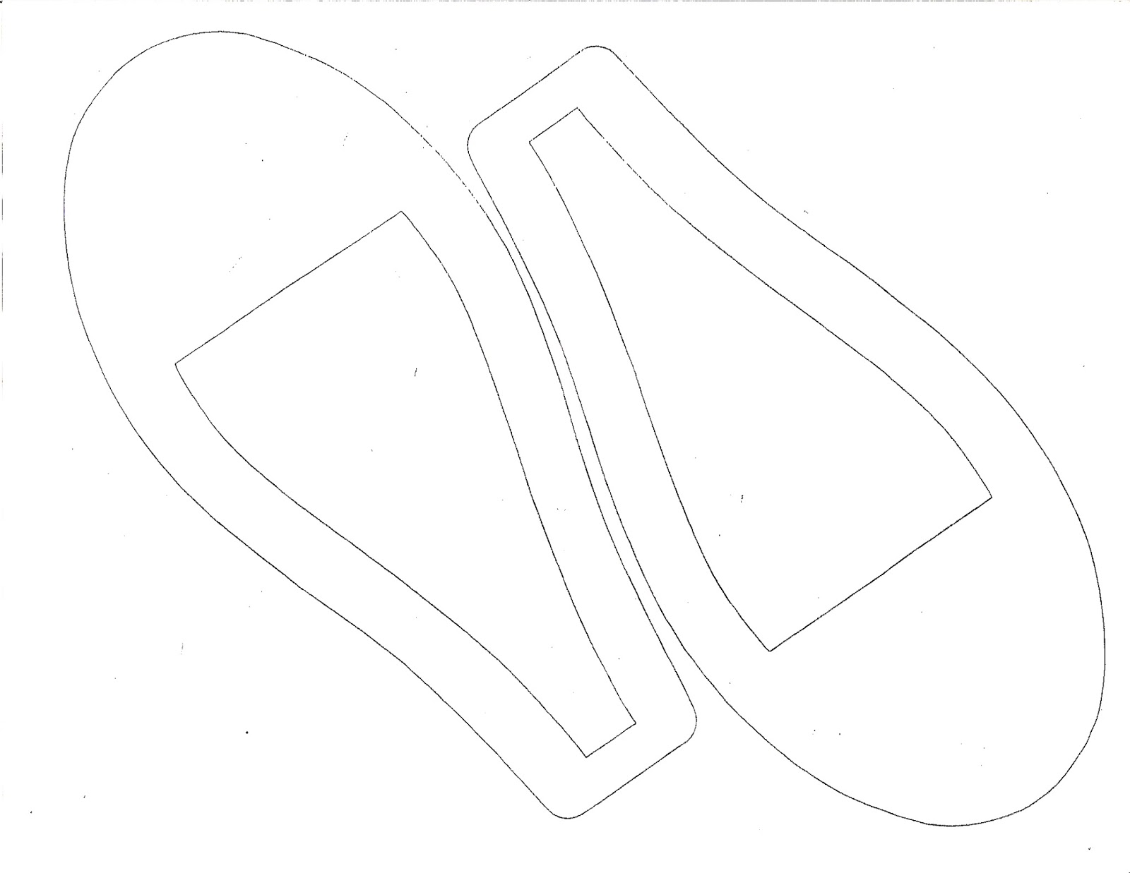
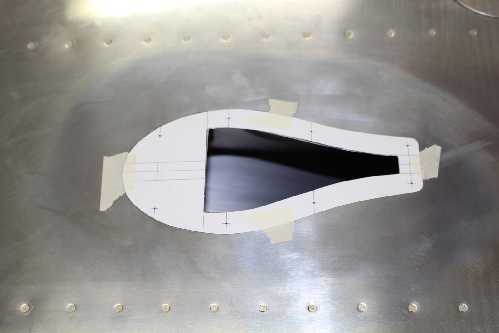
My most recent task was to determine what was required to install the NACA duct in the bottom of the right wing that supplies fresh air to the rear seat passenger. Again, more homework. I reviewed the suggestions - they're not instructions, really - and inquired on VAF if anyone had installed screens. I digitized the templates supplied with the kit, and got a bit obsessive about refining my own version... but I'm happy with the result. I've done the prep work of drilling holes and dimpling, but I'll hold off on actual installation until later. But at least it's planned out now, and will go quickly.


There are still quite a few things to do until the wings can be considered complete. Wiring needs to be installed for the landing, taxi and nav lights, as well as the pitot tube heater and roll servo. The pitot mast needs to be installed and the pitot/angle of attack air tubing needs to be run. The wingtip installation is a big step that needs to be addressed. Although the wingtips won't be mounted until final assembly, there is a lot of fiberglass work that needs to be done to get them ready to mount. I've got the lighting on the way from Van's, and Aerotronics is sending along the pitot tube and wiring I'll need. Hoping to get the wings close to paint-ready next month. Not sure what the sequence will be just yet... but you'll find out. Stay tuned.
Looking good Marty.
ReplyDeleteWell look at you Marty! Back to building an airplane again! I hope to be doing the same thing here shortly. Now you can gloat that you are well ahead of me with the QB Wings and Fuse, and perhaps now I can observe your detailed posts of everything instead of the other way around!! Your progress looks great, and I like some of the methods you used to ensure proper fit of things.
ReplyDeleteI've pretty much decided to get the QB Fuse due to my own project delays, but first need to get my SB wings to the same point that yours are at now.
KPR man! Will you be at Airventure this year?
Bryan
Thank you sir! It's kinda the focus of my life right now... so I better be making progress! Yes, I will be at AirVenture this year. Let me know if you want to meet up again. I believe you still have my cell phone #... if not, I'll send you a PM via VAF. I still have your #... let me know if you'll be there.
DeleteIf your number is the same as it was in 2015 then I still have it. I'm definitely planning on attending Airventure this year so I'll try to contact you when I'm up there.
DeleteOne thing I am curious about after reading your post about the truck delivery - Appears that they did not crate anything and just secured the parts in the truck. Did you pay a crating charge for that? Since I will be getting the QB fuse I'm curious about the details of your truck shipment/crating charges, arrangements, etc.
I was lucky enough to get into Tony Partain's shipping schedule - Partain Trading company. The actual carrier Tony made arrangements with was Stewart Transport. I recommend both highly; see my earlier blog posts for more details. And you are right; if you make arrangements with Tony, Van's subtracts the crating charge... but if Tony puts you in his delivery schedule, you still have to send Van's a written agreement that Partain Trading Company is handling the shipment, and they will prepare the QB kit for Tony's logistical requirements. And order EARLY... I waited over 8 months before delivery.
DeleteAnd yes; cell phone # is the same.
Delete