Wow. When I started this entry, I didn't think I had much to talk about. Turns out I was wrong about that. Get comfy, folks... this is gonna be another long one.
The first task I tackled in January was finishing up some deburring and dimpling of the baggage door parts and removing the top forward skin. That skin ended up hitting the floor when my heater fan blew it off the workbench. One corner was bent slightly, but I managed to massage it straight.

 Then I began to work out how I would mount my manual elevator trim knob. Most builders put it in the left subpanel but that wasn't an option for me. I could have installed it directly into the gear tower, but that would have been awkward to operate and even harder to install. I needed to make a bracket for it, and figure out where I would hang it. I designed a template out of card stock and duplicated it in aluminum. I used a scrap subpanel piece as a material source; it was thick sheet and the pre-bent flange would work well for my purpose. In order to make sure the placement ergonomics would work I needed the throttle quadrant in place. I had ordered the deluxe throttle quadrant, but the quickbuild parts assembled by the factory were configured for the stock throttle quadrant, so some modification was required. I had to remove material surrounding the tabs of two nut plates, but the finished fit would work well enough. I also assembled the aileron trim panel and put both controls in place on the left fuselage side.


I had to determine the best ergonomics for the location of the elevator trim, so I assembled the trim vernier to the test bracket, fitted the seat pans and upholstery, climbed into the airplane and explored my options. It looked like hanging the bracket from the upper aft brace would work; the curve of the flange would nest nicely with the curve of the brace, but I would need a longer bracket to clear the bottom of the instrument panel. Once I was sure exactly where I wanted it, I marked the location, drilled #40 pilot holes in the bracket, clamped it back in place on the brace, match-drilled the pilot holes and final-drilled all holes to #30 for AN470 rivets. I bent the bracket slightly to angle the vernier and allow the cable to pass below the baggage bulkhead. It was then prepped and painted flat black. I drilled 5/8" holes in the front and rear of the left gear tower, fitted the holes with snap bushings and routed the trim cable through the tower. I riveted the bracket to the upper aft brace, assembled the vernier to the bracket and attached the cable. The placement should work well.


I continued to work on the aileron trim panel assembly; cutting the cable to length, drilling the cinch bolt and fitting it to the actuation linkage in the fuselage bottom. This trim apparatus is a bit crude, and I'm not sure I'll keep it attached to the control column, but in any case it is in place and assembled.


At this point it was difficult to decide what to work on next. I had fitted the empennage and control surfaces in anticipation of working on the trim connection, but decided against that. I still needed to get the aft bulkhead tops painted but it was just too cold to mix paint and use the spray gun. To organize my thoughts, I made a list of all the unfinished steps in each of the major construction phases. I decided to start into the wiring phase of the build. Even though I had the assembled, finished and tested panel from Aerotronics, this was still an intimidating challenge. My lack of expertise had me feeling blind and clueless; a familiar feeling. But experience reminded me that I only needed to proceed thoughtfully and carefully, one step at a time, and I would eventually complete the task.
The first issue I chose to face was the location of the ELT antenna. The design of the RV-8 can make this problematic; I decided on the popular option of placing it underneath the empennage fairing. Most builders mount it to the back bulkhead top facing aft, but my antenna had a canted base that prevented me from simply drilling a hole and putting it on. I had to make some sort of angled flange to support the antenna and attach that to the bulkhead. Some planning and careful aluminum fabrication left me with a decent solution. This was one of the rare times I chose to assemble the aluminum parts without painting first, and in retrospect this nags at me a bit. But I really wanted to get it done, and figured if I seal the edges of the assembly prior to painting, it should hold up well enough.


I had to make the hole in the bulkhead top larger to allow a socket to pass through to tighten the ring nut. I'm hoping the additional structure provided by riveting the bracket to the bulkhead will offset the loss of structure in drilling the hole. Later on I happened upon a much simpler approach used by another builder. Instead of making a bracket to deal with the cant of the antenna base, he just drilled a hole in the bulkhead, fitted it with a rubber grommet and stuck the antenna through the hole, wedging the white antenna base into the grommet. D'oh! Why didn't I think of that? That's ok... my assembly is stouter and more stable.
After more head-scratching, I made the decision to go ahead and install the Aerotronics panel and start connecting components. A few minutes of assistance provided by Leo Knowlden and his son Jay, and I had it securely screwed in place. After reassembling the fuse blocks and switches in the subpanels, I had my finished panel in place... and looking so good.


The next task to tackle was placement of the Emergency Locating Transmitter, or ELT. I knew I wanted it in the aft fuselage, but wasn't sure to mount it. I had considered mounting it sideways on aluminum angle brackets behind the elevator bellcrank and pitch servo, but Leo reminded me that it had to be in line with the fuselage with the switch panel facing forward. Gee... I guess I should read the installation instructions, huh? So I did, as well as check on other builder solutions. I decided to form my own bracket that would attach to the right side fuselage longerons and hold the ELT closer to and aligned with the aircraft center line. Tricky... but fun to be able to invent and fabricate my own solution. The design parameters were based off of the distance between the longeron flanges and the 5 degree offset of the fuselage side from the aircraft center line. I could fabricate something using angle stock and flat sheet, but I thought a single piece of sheet bent into the shape of a half-octagon would be more elegant and possibly lighter. I designed a prototype on card stock, bent and taped into shape. I also produced a wooden buck to help me set the 45 degree bends required in my design. The card stock prototype seemed to fit well and verified the design parameters, so I digitized the design into Photoshop blueprint before transferring it to aluminum sheet. Some careful cutting, hole drilling, filing and deburring produced a decent flat blank.


Now it was time to figure out how to bend it into shape. Leo has a sheet metal brake in his shop that he offered to let me use. But I would have had to make arrangements and schedule the work, and I wanted to get it done sooner. So I thought of ways that I could make the bends myself, using my shop vise, C-frame table, seaming tool, various clamps and the steel I had on hand, such as carpenter's framing squares and my backriveting plate. It wasn't easy and the bends weren't as perfect as you'd get from a sheet metal brake, but I did get the part into a workable shape. I wanted the front and rear flanges to overlap so that I could rivet them together to make the part rigid. Getting those rivet holes drilled in just the right place proved to be trickier than expected. I did a lot of double checking during the process, but after the part was dimpled and riveted, it didn't quite fit as well as I had hoped. I wanted the mounting flanges to sit on top of each longeron without having to pull or push the now-rigid part into shape and that required the use of fluting pliers to draw the part together to fit right. The bracket had to be removable, so I planned to bolt it to the longerons with 6-32 x 1/2" screws, washers and lock nuts. Match-drilling the mounting holes was another tricky task. Eventually I ended up with a serviceable bracket... and yet another part that would be waiting awhile for paint.


At this point I unwrapped the avionics wiring harnesses and started planning installations, beginning with the pilot and copilot headset jack panels, USB ports and accessory power port. I had to buy hole saws for some of the planned holes and spent a lot of time agonizing over the best placement of the jacks and the wire routing they would require. I also made the first connection to the panel by plugging the control stick wires into the harness. This was a symbolic gesture; the wires had yet to be routed, but this was the first of many connections to be made.


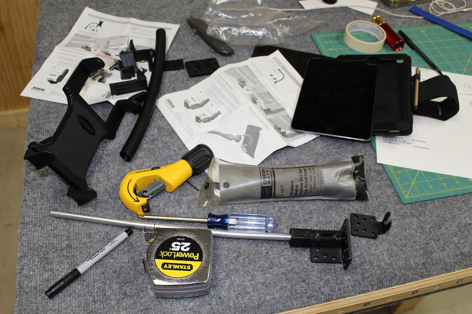
One cockpit accessory I knew I would need is an iPad holder and stand. I chose an Akon car stand and modified it to suit my needs. It took a while to decide the best way to install it, and I eventually chose to bolt it to the right mid cabin cover. This is a somewhat thin panel so I knew I would need at least a doubler plate and possibly some reinforcement angle to stiffen the panel. I made up the doubler plate out of aluminum sheet stock and used the stand bracket to match drill the screw holes in the doubler plate and mid cabin cover. I got cap screws, washers and lock nuts for the mounting bracket and had to modify the base of the pedestal for clearance. With everything temporarily assembled and in place in the cockpit, I was impressed. This should work well. It's exciting to be at this stage of cockpit assembly.


Doing neat wire routing means passing wires through bulkheads, and planning such wire routing requires a lot of thought. The bulkheads have some wiring holes already drilled, but more are usually required. The lightening holes are a potential solution that has its own set of issues. Their size doesn't match any readily available grommets or snap bushings. Scouring a hardware store for a solution, I though of getting these PVC couplings and cutting them down to suit my purpose. It's a viable alternative, I suppose... but they're big and clunky, and in the long run I will probably opt for other solutions. But they were worth a try.


Next work included routing the control stick wire and drilling panels for the audio jacks and adapters. I had drawn some Photoshop blueprints for jack layout and printed templates for drilling the holes. I drilled one test panel for the large adaptor holes to make sure the spacing would work. Then I started with the pilot's jack panel in the right side console, drilling pilot holes through the template and finish-drilling with a Unibit. The harness included three audio jacks each for the pilot and copilot. One was a Lemo 5-pin connector used by some headsets; the other two are standard mic and phone jacks. I'll be using the standard jacks, with the Lemo jacks available under caps. When I fitted the standard jacks for the first time I realized that they used isolation washers with small flanges designed to prevent contact between the jacks and the panel, so I had to resize those holes from 3/8" to 7/16" and altered the blueprints accordingly. It was pretty cool to see those jacks in place for the first time.


This got me to thinking about all the additional labeling I would need in the cockpit. The panel is nicely labeled and I have other placard decals that are required, such as the EXPERIMENTAL sticker and the Amateur Built disclaimer that are part of my registration kit. I also want labels for all the jacks and adapters, the fuel selector valve, the aileron trim and the elevator trim. Since it would look best if they matched the script and style of the instrument panel graphics, I asked Jason at Aerotronics if they could make me some decals. He said they could; they use Corel Draw for that work. I don't have that program, but I could generate some more Photoshop blueprints and they could use those specs to make up the decals. I already had the layout for the jack panels, so I started working on the fuel and trim decals. The fuel valve has four positions - Left, Right, Off and Off - all equally spaced 90 degrees apart. I knew they were clocked at approximately 45 degrees, so I made a card stock template, taped it to the left mid cabin cover and checked the positions of the valve against the template. I learned that they were actually clocked 60 degrees counterclockwise from top vertical, so I altered the blueprints. Another template confirmed my measurements. The aileron trim was easier; I just needed to duplicate the arc and length of the lever slot. The elevator trim was the easiest; I just had to make sure of the direction of actuation and make a representative knob and arrow. When I was satisfied, I generated negatives and printed samples with black backgrounds and white lines and lettering.


Drilling the copilot jack holes was a bit more difficult because the panel was already part of the airframe. I used an angle drill to set the pilot holes and was able to enlarge them from underneath with the Unibit. Routing the copilot jack harness was even more problematic. Since everything was pre-wired, I had to route the harness through holes that were 1" in diameter or larger. This limited my options, especially when it came to dealing with the spar box. I ended up routing the harness down the right gear tower and out the 1" hole in the bottom; through the open rectangle for the control column, through the floor ribs and up the right side of the fuselage. I had to notch the floor support angle and the right main floor panel to bring the harness up to the jack panel, I wrapped the exposed run with flexible conduit, but decided I needed to make a cover panel to protect the jacks and wires. Luckily, the factory had already drilled holes with some nut plates already in place. I just needed to make a panel that would fit the hole layout as well as the stagger between angles, bulkheads and the aft passenger panel. I was glad that the forward two holes didn't have nut plates installed, because I could use the gap between the jack panel and the bulkhead to my advantage by putting the forward nut plates on my cover panel, sliding the forward end into the gap between the bulkhead and jack panel and secure by putting the screws through the bulkhead holes and into the nut plates in the cover panel. I was pleased with the result, and can't wait to see it painted. When I made cut out the decal template to check jack placement, I learned that the holes weren't quite evenly spaced. The middle jack hole was displaced about 1/16" aft. I modified the blueprints again, glad that I had checked it before submitting the blueprints to Aerotronics.


Next came magnetometer placement. I had learned a bit about the subject in previous research. But the newer Garmin GMU11 is a much smaller unit than the older magenetometers. However the requirements for spacing away from ferrous and current-inducing objects are the same. I had some ideas and discussed them with Jason. He had some better ideas and sent me drawings, photos and instructions on the best way to fit the GMU11 in an RV-8. I made a removable bracket out of some angle stock and flat stock, securing it with more 6-32 hardware. Like the ELT bracket, it can't be final installed until after the aft fuselage skin is in place, and is awaiting paint... although I did prep and prime the bottom of the flat platform before riveting it to the angle stock.


One small job was locating my cockpit light. I chose to mount it on the right bulkhead cap. This might become problematic if I ever have to remove it; that bulkhead will eventually be riveted in place. But the red LED light should last the life of the airplane, so I'll take that chance.

Jason suggested that I mount the remote transponder in the forward baggage compartment, so I spent a lot of time planning that installation. I decided to mount it on the removable forward baggage side panel. This would keep it out of the way, minimize exposure to damage and facilitate harness routing. This same panel turned out to be a good place to mount the EIS module that controls engine monitors and instruments. I studied the installation manual of each unit and planned accordingly, taking serviceability, connector access, panel screw access and other factors into consideration. One factor was the proximity of the rudder cable attachment hardware on the back side of the panel. I would need to make brackets for the remote transponder rack and flush rivet them to the panel. I would also have to use flat head screws to mount the EIS module because the arc of the rudder cable hardware intersected the hole location and I couldn't risk having a rudder cable bolt hang up on a protruding screw head. That required dimpling the screw holes in the panel and on the module flange. I didn't have dimple dies of that size; I had to order them... and thus began another peripheral saga.
I ordered #10 dimple dies from Cleaveland Tool, along with some other electrical tools. They shipped it USPS Priority Mail, and it never arrived. The tracking system showed a delayed delivery with no updated date... for the next week. I sent email inquiries and Cleaveland did the same, and eventually I got a call from the tracking department that indicated the package was still in Iowa, although they weren't certain where, or why. They suggested that Cleaveland Tool pursue the issue on their end, and attempt to recover the merchandise. Cleaveland had already reshipped the order by then; I'm hoping they are able to recover the original package, because it wasn't cheap, and they didn't charge me to reship. This is the second time USPS has lost a delivery to me from Cleaveland. The first time USPS tracking showed it as being delivered, but it wasn't. Cleaveland has been very honorable about both issues, and sent replacements with no charge and no dispute. But rest assured that any more future shipments to me from Cleaveland will be via UPS... including the reshipment that arrived earlier than expected... they actually arrived while I was on the phone with Annette at Cleaveland Tool, discussing the situation!
To fabricate the transponder rack brackets, I sacrificed the blank instrument panel I had bought from Van's. I had used it as a subpanel alignment jig when prepping the top skin and had intended to return it for credit. But it was perfect material to use for that application. It was thick sheet stock with a perfectly bent flange at the bottom that I could cut to any size, instead of using traditional angle stock with flat stock riveted to it. I used the rack as a template to lay out the bracket mounting screw holes. The transponder fits snugly in the rack, so I had to use flat head screws to mount it to the brackets. I made sure the rack was spaced off the side panel just a bit to allow the transponder to clear the baggage tray assembly screws when inserted or removed from the rack.


After drilling the screw holes, I laid out and drilled a row of #40 rivet holes in the base flange of each bracket. Bolting the brackets to the rack, I placed the bracketed rack on the side panel, determined the ideal placement and match-drilled rivet holes through the side panel. The panel was deburred and dimpled; the bracket bottoms were machine countersunk because of the thicker material. I prepped and primed the brackets and riveted them to the side panel.


Placing the side panel in the fuselage, I determined where I wanted the cables to pass through the aft flange of the panel. I drilled a 7/8" hole near the top and cut a channel from the hole to the edge of the panel flange so that I could slip the harnesses through to the hole without needing clearance for the large connectors that terminated each harness. I had a large grommet for the hole that I cut to allow it to be wrapped around the cables and then inserted in the hole.


I planned to mount the EIS module alongside the transponder rack with the connector ports facing forward. I had the routing for the outbound connector harness to the panel the solved... now I had to figure out how I wanted to route the inbound harnesses from the engine sensors. I could have gone straight through the firewall, but not knowing where I'd have room, I elected to use one of the existing firewall penetrations that was (probably) for wiring anyway. There were a number of ways to route the harnesses to that hole, but the most discrete and protected course was along the firewall, underneath the the forward baggage support angle. It fit well there, and could be secured by cutting a notch in the forward top corner of the side panel so that when the side panel was fitted, it pinned the harness in place. For the other end I fabricated a retention tab that I could bolt to the other vertical angle on the firewall that would pin the harness. I did some research (and checked with Jason) to made sure that all the wires in that harness would terminate forward of the firewall before wrapping the harness in flexible conduit and pinning it in place.


I couldn't complete the installation of the rack or the EIS module until I had dimpled the side panel for the EIS mounting screws... and at that point I was still waiting for the missing package that held the dimple dies. While waiting on the resolution of that issue, I took care of a few other tasks. I mounted the ground block to the upper forward brace, fabricated a mounting plate for the power stabilizer module and bolted it to upper aft brace. I also decided to rivet the doubler plate to the mid cabin cover and make up that reinforcement angle to increase the rigidity for the iPad stand. I laid out and drilled the rivet holes in one flange of the angle and lightening holes in the other. I match-drilled the rivet holes in the cover, dimpled the cover holes and machine countersunk the rivet holes in the angle. A quick prep and prime of the doubler plate and reinforcement angle, and I riveted them in place using the C-frame to set the rivets. I inspected my work, and to my horror I discovered that most of the rivets holding the reinforcement angle set proud, sticking up like sharp-edged warts. I very carefully drilled them out and set better ones. The only evidence of my rework was a very small chip of paint missing from the edge of one dimple, and I'll live with that.


I finalized the design of the decals and placed the order with Aerotronics... more on that later. I worked on routing the wiring for the tail strobe, drilling holes for rubber grommets, putting heat shrink tubing on the wires where they passed through bulkheads and drilling holes for mounting adel clamps. I snaked the tail wires through the flexible conduit run holding the copilot jack harness to avoid another penetration of the spar box. I ran the line for the ELT to the instrument panel switch and the line that carries GPS data to the ELT using zip ties and flexible conduit where needed.


When I finally received the dimple dies, I dimpled the EIS module flanges and the side panel for the flat head screws. I checked the fit of the panel in the fuselage and had to enlarge the notch for the EIS harness coming from the firewall. I had originally planned to screw down the side panel before installing the transponder rack in the brackets, but after the test fit I realized that limited access required me to put the rack in the brackets first. In my haste, I almost put the rack in flipped, effectively masking the transponder's securing tabs... but I caught it in time. Getting to the screws inside the rack was tricky, which was the reason I chose flat head screws with a hex head instead of a Phillips or Torx head. I had to tape the Allen wrench to a long screwdriver to get it to the bottom two screws, but it wasn't as hard as I thought it might be. Once the rack was attached I could screw the side panel into the fuselage, hopefully to stay. I was worried that the rack would make it impossible to reach two of the floor screws, but with an angled screwdriver it was manageable if not awkward. I was actually surprised that installing the side panel turned out to be easier than bolting the EIS module to the side panel afterward. Because of the dimples in the panel and the flange I had to use progressively stacked washers to make sure the lock nut tightened the flat head screws fully into the dimples. On the bottom flange, working blind in a tight space, that turned out to be a real pain... especially because the harnesses had to be connected before the module was bolted down, and the tension of the flexing harnesses kept trying to pull the loose module off the screws. Just another jig in the jigsaw puzzle. When it was done, it felt like a major step forward, and it looked that way too.


Now, about those decals...


I had put a lot of effort into making sure my drawings and specifications were accurate. After a lot of revisions and refinements, I assembled a .pdf order document with all drawings, specifications and instructions for the decals. Jason sent me a proof, we discussed refinements, and he send me a revised proof that I approved. I also ordered coax antenna cables and other wiring supplies I needed.


The Aerotronics package arrived today, along with a package from Aircraft spruce with battery cables and lug ends. Writing this entry has taken all day, and during my afternoon break from writing this, I did an inventory of the packages. All seemed well at first, until I realized the fuel selector decal was about half scale. I had a hunch why this might have happened, and I was right... about being wrong. My drawings were pretty close to scale, but if you look very carefully at the specifications below the fuel valve in my order, you'll see that I wrote "Outer circle 3" max diameter." What I MEANT was "Outer circle 3" max radius"... which is why the decal was half the size I wanted. Furthermore I didn't check the specs spelled out in the proof; I just glanced at it... the shapes looked right and I assumed the drawings weren't to scale, even though it says quite plainly that the fuel valve decal would be 3"x 3". Oops... my bad. Oh well. As long as I had to reorder the fuel valve decal I asked Jason if it would be possible for the center dot in the elevator trim decal to look more like the bumpy knob represented in my drawing. We'll see what happens.
So... FINALLY... I'm caught up here. Just in time too. Although my prop is delayed more than two months and I still don't have a delivery date, I do have a build date from Barrett for my engine. My next entry will cover my trip to Tulsa, documenting the engine build and run-in, and bringing it home with me. Stay tuned; you'll be hearing more soon.
No comments:
Post a Comment