I must admit I'm getting pretty tired of the word "distractions". It's been another couple months of working an hour here, a couple hours there; progress has recently slowed to a crawl. I've had some good reasons, of course. I flew into AirVenture this year on Thursday aboard the Yankee Air Museum C-47 Hairless Joe. It was a whirlwind visit; great fun but I couldn't fit in nearly as much as I wished. But I did keep my promise to myself that I would get more work done on the plane by spending only one day there. July's other big event was getting to ride with the Commemorative Air Force Air Power History Tour in the famed B-29 FIFI; that turned into a four-day event for me. I made videos of each experience and posted them on my YouTube channel; here are the links:
My AirVenture 2019My Date with FIFI
They're both pretty long videos; OSH is almost an hour and FIFI is almost two hours. It took a LONG time to get each one assembled, and I swear I'll never make one as long and complicated as FIFI again. But I'm proud of the way each one turned out, and true warbird fans should enjoy them.
The biggest distraction by far was my daughter Naomi's wedding, which took place on August 11. I'm still recovering; more on that later. But it was (and always will be) worth all the effort. I'm taking advantage of the break in building continuity by getting this post done now. Hopefully that will clear the decks for awhile so I can continue working at a much better pace.
My last post ended with preparing for riveting on the top forward skin. I determined which holes would require Cherry Max blind rivets and which ones would use solid rivets by climbing in the cockpit and checking access to the shop heads. I marked the holes as appropriate used the Cherry Max depth gauge to determine how many of each size Cherry Max blind rivets I would need and ordered the blind rivets. I reamed out the blind rivet holes to #30 and removed some temporary rivets installed by Van's during quickbuild construction. The top skin was removed; holes were deburred and chips vacuumed out. I also remembered to attach the scat tube from the fuselage NACA vent to the eyeball vent in the panel. In the process I discovered some hidden bulkhead tabs that had not been drilled in the quickbuild process. Over the course of clecoing on the forward top skin numerous times, they had been bent slightly, and it took some massaging to get them to lay flat against the longerons and match drill the holes.


The holes requiring blind rivets needed to be re-dimpled to #30 size. I used the squeezer and C-frame table to dimple the forward top skin, baggage door support strap and bulkhead tabs where possible. Some holes required the use of close-quarter dimple dies and some holes along the longerons were lightly machine countersunk to allow the skin to fit better. With all the resizing and dimpling complete, the forward top skin, forward and aft baggage door support strips and aft support clips were all prepped, wash primed and primed. When the primer was dry, the top forward skin was masked and selected areas were painted flat black, along with the aft support clips and the top surface of the Garmin GA 35 GPS antenna puck. Garmin recommends not painting the puck, but the shiny white finish would have created a big reflection on the inside of my windscreen. After checking with Garmin, they agreed that it could be painted flat black as long as the paint was non-metallic. In preparation for this process and more painting to be done this summer, I went through my Sherwin-Williams paint supply inventory and found much of it expired. I spoke to Blend Supply and determined which supplies could still be used, and which ones needed to be replaced. I ended up removing many hundreds of dollars worth of paint, hardener and reducer from my stock, ordered some replacements and will have to order more in the future. Important and Expensive Lesson Learned: don't order paint supplies until you're sure you will need them.


Once all the paint dried it was time for some actual assembly. The GPS puck and ventilation fans were bolted onto the bottom of the forward top skin and the aft support clips were riveted to the skin. The skin was clecoed back onto the fuselage and the overall fit was checked again, including baggage door fit, fan wires and antenna coax cable layout. I had relieved the bottom edges of the skin when I prepped it for paint, but they still had to be massaged with a hand seamer to get them to snug up against the fuselage side skins. This took a few tries, and I eventually had to remove the skin and work it on the C-frame table to get the edges where I wanted them. I reviewed the instructions for installing the forward baggage door to make sure I grasped the process completely. I even called Van's Builder support and reviewed my plan with them to see if they had any additional advice. Once this skin goes on, it goes on for good. I had to make sure I was truly ready, and I was. I took a deep breath and warmed up by setting two missing rivets along the longerons aft of the forward top skin on each side of the fuselage, then set the row along the baggage door opening that didn't involve the forward top skin. Then I started to set some of the solid rivets along the instrument panel and baggage bulkhead rows, beginning at the top center and working down evenly. I didn't set many; just enough to secure it in place. I took another big breath, and started setting the Cherry Max blind rivets. I was glad to spend the money for their blind rivet puller; I couldn't afford any problems with these rivets. It turned out to be easy work that went quickly. I found myself wishing I had used Cherry Max blind rivets on the entire skin, but there was no changing the plan now. It took awhile to arrange for a second person to buck the remaining solid rivets, but at one of our usual PTK breakfast gatherings I met Gary Konrad, and he graciously volunteered three hours of his time after breakfast. This was very fortunate. Gary is an accomplished builder and craftsman who has built several airplanes including an RV-7. We spent a lot of time talking as we worked, and enjoyed the process thoroughly. We had to custom-cut some rivets for certain holes, and I was glad for his input. The work was done properly, and we were both pleased with the result. After Gary left, I secured the aft support clips, match-drilled the #30 holes into the windscreen support weldment and set them with blind rivets. Riveting the firewall and baggage door hinge rows would be done after the cowling was completed. Another milestone had been reached: the top forward skin was in place to stay.


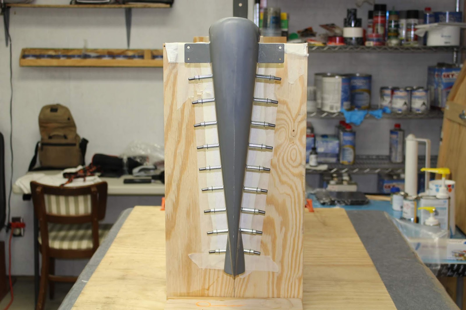
And now for something completely different: fiberglass work. Despite doing several successful practice projects, this was another skill set that I approached with hesitation. I put some time into doing some refresher homework, ordering more supplies, and generally avoided doing real work by doing little chores like applying the Velcro strips for my front seat upholstery. Another deep breath... and got to work on the vertical stabilizer and rudder tips. I had started work on all the empennage tips a long time ago, drilling pilot holes in the fiberglass parts and checking initial fit with clecos. I restarted the process by reaming the pilot holes out to #30 for the blind rivets, dimpling the aluminum holes and gluing reinforcement washers on the inside of the upper tips with epoxy. Once the epoxy cured, the dimple side of the fiberglass parts were machine countersunk with special abrasive bits supplied by Lancair. Walt at Synergy Air had taught me the secret to bonding fiberglass to aluminum was to use Pro Seal adhesive/sealant as a way of preventing the fiberglass from shifting on the aluminum when heated, due to different expansion coefficients of the materials. I had two tubes in stock that had expired for sealant duty, but would be adequate for bonding. The rudder tip was the first to be bonded and quickly blind riveted. An end cap for the vertical stabilizer tip had been made previously, using composite material made at the Synergy Air quickbuilding course. I had decided to use West Systems epoxy because their "one pump of resin/hardener" system made getting the right mixing ratio so much easier. It's not the strongest on the market, but it is quite adequate for the work required on RV aircraft. I experimented with the process, noting the cure time and other properties before glassing the end cap into the vertical stabilizer tip. Mixing up some flox to make a very slight concave shape to the end and applying peel-ply created a part that required very little additional shaping. When cured, it was bonded and blind riveted to the top of the vertical stabilizer. One unfortunate issue was that once again, my Surebonder blind rivet puller broke two of the rivet mandrels long. The problem was discussed again in depth with Cleaveland Tool and others. And once again, Cleaveland Tool stood behind their product. They insisted on sending another new one, and asked me to send back the other two for examination. I did as requested, although I did keep one of the mandrel setting tips that I had modified to help re-break any long mandrels. To date, I haven't heard any feedback from Cleaveland, but the support they've shown me will keep me a very loyal customer. I managed to cut the long mandrels off without causing any damage. I mounted the rudder onto the vertical stabilizer to check the initial fit, which wasn't bad... but wasn't great. Some filling and sanding would be required.


The top of the rudder tip would need to be built up to match the elevation of the vertical stabilizer tip. I did it in two stages, adding successively smaller layers of fiberglass mat and capping it with filler. I bought two kinds of filler; Aeropoxy Light and SuperFil. Based on reviewing my fiberglass class notes I thought they might have slightly different applications, but in practice they seem interchangeable to me. I bought a kitchen scale to weigh the filler and catalyst to obtain the 2/1 mixing ratio and experimented with Aeropoxy Light to get a feel for working with it before applying over the cured fiberglass mat. Once the filler had cured I did some rough shaping, using the vertical stabilizer tip as a guide, before removing the rudder and putting it into the table jig for continued shaping, adding filler or spot putty as needed to get a smooth shape. During curing periods, I began work on fitting the rudder bottom, match drilling the #40 holes that would be used for either blind rivets or screws. I also began filling and smoothing the vertical stabilizer tip.


While working the rudder tip, I discovered a loose rivet, which was safely removed and replaced. Based on my experience with the vertical stabilizer tip, I realized it would be much easier to attach the inside fiberglass mat to tip end caps before glassing them into the tips, so I went ahead and applied mat to the caps I had cut for the horizontal stabilizer tips. I also began working on the tail strobe area of the rudder bottom, squaring off the mating surface to allow a flush bonding of the tail strobe adapter ring. Because the squaring process removed a fair amount of the part's fiberglass mat, I built it back up with three more layers of fiberglass mat before shaping it and bonding the adapter ring in place. The ring is held with both epoxy and rivets; once it was bonded I built up flox around the edges to provide a little more strength and enough material to shape properly. I also added flox around the shop ends of the blind rivets to help reinforce the assembly. Another issue to be addressed was grounding the Suntail housing. I wasn't sure I'd be able to ground it with a ring terminal with the rudder bottom permanently affixed to the rudder, so I decided to attach a wire to the adapter ring. I drilled a small hole into the inner surface of the ring, soldered the wire in place and reinforced it with epoxy.


I continued to work on smoothing the attached tips, touching up low spots and spraying with filler/primer to get an idea of how it was coming along. I wanted to cover and smooth the blind rivets but keep the solid rivets in the aluminum visible. I continued to alternate between the tips and rudder bottom, working on one while the other was curing or drying.


When the rudder tip was looking pretty close to the way I wanted it, I mounted it to the vertical stabilizer to see how the tip shapes lined up, and I got a bit of a shock. It wasn't very noticeable during earlier assemblies, but the tips didn't line up very well. The left sides lined up nicely, but on the right side the rudder tip bulged out of alignment from the vertical stabilizer tip. It looked like the rudder tip was canted to the left... almost like the entire counterweight section was slightly canted. I was uncertain how much of an aerodynamic effect this would have, but it didn't look right, and I didn't like it. I wasn't sure how to approach this issue. There was only so much material I could remove from the rudder tip before I'd thin the glass too much, and I really didn't want to glob a bunch of filler on the vertical stabilizer tip to make it match the rudder tip. After conferring with some of my PTK friends and looking at their airplanes, I decided to carve off some of the rudder tip, epoxy it and smooth it, and see how much improvement I could gain. At this point I think it's acceptable; I'll make a final determination after spraying on more filler/primer. Meanwhile I continued to massage the tail strobe area of the rudder bottom to get it smooth and even.


With the aft end of the rudder bottom shaping up well, it was time to address the issues on the forward end. The rudder bottom needs to be notched on either side of the forward end to allow it to fit around the rudder horns. Laying out these notches was tricky because the horns are at a different angle in relation to the rudder bottom edges. When I did the initial work awhile back, I was successful in cutting the notches perpendicular to the bottom edge and got the angle correctly configured. But in checking the fit, I realized that ideally the notches should have been perpendicular to the rudder end and angled in relation to the rudder bottom edge. I was glad it was fiberglass, because I could cut a triangular section out of the aft end of each notch and graft it onto the forward end, thus creating an angled notch. I took measurements with the rudder bottom in place and realized that for best fit, the two sides of the notches would be at slightly different angles. I drew the cut lines for the aft edges and cut off the triangular pieces. Again, checking them with the bottom in place, I determined the finished shape requires to fill the front edges, cut the triangular pieces to fit, and grafted them onto the front edges of the notch with a couple fiberglass mats on the outside and some flox on the inside. I couldn't add much thickness to the part in those areas because if I did, it wouldn't fit well. I used small stir sticks as backing forms to help hold the triangles in shape during curing, and that worked out well. Some more filling and massaging and I was happy with the grafts. I'd been worried about having to do that modification for a long time, but it actually turned out to be fun.


Circumstances dictated a couple diversions from empennage work. The dehydrator plugs in the engine needed their dessicant changed, so I took care of that. We had a short heat wave in late July, so I thought it would be a good time to start some canopy work. I masked off the cockpit, got the canopy off its perch in the garage, placed it on the fuselage and pondered just how I would go about getting it trimmed to fit. More study and more planning were required.


I changed course once again to address another issue that had been nagging at me for quite a while. When I ran the cable for the tail strobe, I thought I could get away with routing them through a tab notch in the aft bulkhead. With the rudder bottom taking shape, it was time to find out if that would work. I raised the tail, mounted the vertical stabilizer to the fuselage, hung the rudder with the bottom clecoed in place and checked out how the cable might run. At this point I still hadn't fully committed to riveting the rudder bottom in place; I had to see what it would be like to route the tail strobe cable with the rudder bottom in place. Routing looked good; I had enough slack that I could pull the cable all the way through the rudder bottom and out the tail strobe fairing, even with connectors in place. But I didn't like the way I'd have to route the cable from the bulkhead notch; it just wasn't the right way to do it. I had hoped to avoid drilling a hole through the vertical stabilizer aft spar, but it would be necessary in order to keep the wiring safe and stable. I removed the rudder, did some measuring, checked access on both sides, laid out the location, took a deep breath and drilled a #40 pilot hole all the way through the aft spar and aft bulkhead. Checking the layout on the inside and outside showed it to be a good location, so the pilot hole was carefully enlarged to 1/4". I removed the vertical stabilizer and deburred both sides of the holes in the spar and bulkhead. I rerouted the cable through the aft bulkhead; the additional heat shrink tubing layers I had added worked well in the new location. I couldn't use a grommet in that location because of the tight fit of the vertical stabilizer spar against the aft bulkhead, so I mixed up a small batch of flox and applied it around the cable on the forward side of the aft bulkhead to help stabilize the cable in place. I will have to route the wires through the aft spar as the vertical stabilizer was mounted to the fuselage during final assembly. But at least the problem was solved for now.


More rudder bottom work. At this point I committed to mounting the rudder bottom to the rudder permanently. I knew the wiring would work; I wouldn't have to hassle with installing nut plates; it would be easier to paint and it would look better. With the modifications done to the notches, I could lay out and drill the rivet holes that would secure the forward ends of the rudder notches to the aft spar flanges. The holes were laid out and drilled in the flanges first, then I used a strap duplicator to match drill the holes in the rudder bottom.


One remaining task on the vertical stabilizer was to rivet nut plates on the bottom edges that held the empennage fairing in place. I did some research and discovered I was missing a drawing from my empennage plans; DWG 43. Fortunately it could be found on the digitized set on the thumb drive I purchased from Van's; I printed a copy for reference. The pilot holes for the screw locations were pre-drilled in the skins from the factory; I reamed them out to #30 and used clecos to hold the nut plates in place while I match drilled the rivet holes, then drilled the screw holes out to #12. After deburring and dimpling the skins and nut plate wings, I riveted the nut plates in place. I think that's the last fabrication to be done on the vertical stabilizer before painting.


Since I was getting close to painting the rudder and vertical stabilizer, it was time to design a stencil for tail numbers, similar to the serial numbers marked on WWII aircraft. Since my actual serial number is only five digits and WWII serial numbers are usually six digits, I made up my own numbers for the tail. Experiments with layouts revealed that a 600 point Arial typeface would be about right for the area I had to work with; four digits on the vertical stabilizer and two digits on the rudder. I came up with this rough design, converted the size to inches and ordered two stencils from stencilsonline.com.

Time to work a little bit more on the rudder bottom. Most of the rivet holes were upsized to #30 for blind rivets. The exceptions were the aftmost holes which would use limited-clearance blind rivets, and the forward holes which allowed squeezing solid rivets.


Time to switch gears again, back to the canopy. I knew I'd need to make some sort of canopy cradle that would hold it securely as I worked on the bottom edges. I came up with one design and built it out of 2x4 studs, with a moving blanket for a sling. Testing the fit led me to redesign the ends so that instead of a rectangular shape, I'd have a lengthened hexagon. Final fit is just a hair snug, but secure. I experimented briefly with different ways of working the edges, as they must be smoothed after each cut to prevent cracking.


I called Van's to get more info on pro seal (brand name: Chem Seal). In the past I had elected to buy the mixable syringes from Van's when needed, but they expire fairly quickly and I wasted a lot of it because once it's mixed, it must be used or thrown out. I was finally convinced to buy it in bulk and mix my own quantities. In the long run it was cheaper and much less wasteful. Once I had it in stock I was ready to attach the rudder bottom permanently. After reviewing the instructions and prepping the parts, I mixed a small batch, applied it to the mating surfaces, fit the rudder bottom and quickly riveted it in place. With the rudder structurally complete, I could calculate the layout of the red and white stripes that will be painted on the rudder. I experimented with it briefly, marking the possible layout with small strips of tape. Later on I added some flox and SuperFil in some areas to smooth out the assembly; sanded, reapplied, sanded, smoothed, etc. I also filled the bottom of the rudder counterweight to help keep the counterweight screws secure. It has not been sanded yet.


Work stopped in early August as preparation for my daughter's wedding took priority. She was married last Sunday and I thought I'd get back to work right away, but my body had other ideas. As a byproduct of having my nose hair waxed prior to the ceremony, I contracted a staph infection in one nostril that had me walking her down the aisle looking like I was wearing a clown nose. It hurt like hell, and I won't even begin to describe how gross it got. I couldn't wear a respirator until it was under control, and as of today it's finally looking like it's healing. In the meantime, I got this blog done, so that's some kind of progress. I'm feeling caught up now; the wedding's done, the videos are done and the next distraction in the appointment book is in late September. Time to get back to work... that is, if I put off an idea I had yesterday for another airplane related video. It will be short, fun to make and extremely silly... but the plane must take priority. Summer is going by too quickly. I have to start working more than one or two hours a day on it to achieve my goals before winter. I'll keep you posted; stay tuned!
This comment has been removed by a blog administrator.
ReplyDeleteNice Blog, Blind rivets are mainly used in applications where there is no access to the rear of the joint.
ReplyDelete