Sunday, November 8, 2015

Elevator Horn Rework

     In the course of going through the test fitting of the elevators, I learned much to my dismay that the holes I drilled in the elevator horns didn't align precisely enough with the center bearing race.  The right one might have been close enough to use, but the left one was off by quite a bit.  Apparently, the copper bushing I used during the drilling process, along with a taped-up #40 bit, wasn't accurate enough, and the problem was multiplied enough during the upsizing that the holes were off.  I called Van's, and they said I needed to have the holes TIG welded closed, and then redrilled.  Sure, that would mess up the powdercoating, but that could be primed over.  Lots of other builders have gone through the same process, I was told.  In the big scheme of things, the rework wasn't such a big deal, and it was worth it to have no binding in the elevator travel.  They also made recommendations on some better bushing stock to use, which I did manage to find at one of my local hardware stores.
     I got in touch with Jeremy Tingley, a local welder that came highly recommended.  We discussed the project and the possibility that the weld might be difficult to drill through.  He said he could use a softer alloy filler rod if necessary.  I carefully wrapped up the elevators and headed to his home shop, where he got the job done in less than an hour.
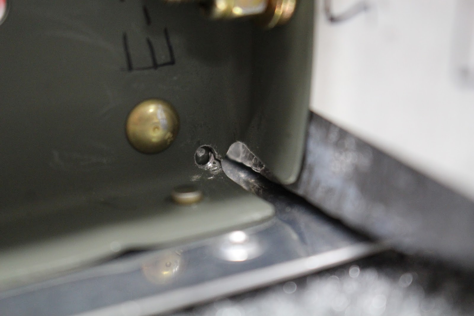
     Returning home, I set up to redrill the holes... and hit a hardened steel wall.  The welds were an absolute monster to drill out.  I went back to the hardware store and bought cobalt bits, but even those just sat and spun on the welds like an ice cube on a skating rink.  In a panic, I did some more research, and learned that I should probably anneal the welds, but I don't have a torch that will generate that kind of heat.  That would also burn the powdercoating, and possibly weaken the aluminum if the heat spread.
     To make matters worse, during all the repeated remounting and removal the right elevator counterweight managed to hit the floor again.  It was a light hit... but it did move the counterweight again, and when straightened I was left with two tiny cracks in the end rib webs.  Damn!  I got those stop-drilled and stabilized, but that didn't make me feel any better about the whole situation... which was starting to stink to high heaven.
     I couldn't sleep that night... so I just went back out to the shop and continued to work on drilling until I got a small bit to penetrate each one.  Using a lot of different methods, I did finally get both holes to size, and to my immense relief they were drilled straight and true.  I got them prepped and primed, and the next day I reassembled all the empennage pieces onto the stand with the proper bolts and washers in place.  I used standard nuts for the preliminary fitting, saving the locknuts for final assembly.
     The following day I cleaned up the shop, and made up a cover for the vertical stabilizer assembly.  The material I was going to use for the horizontal stabilizer covers was used up in masking and painting, and it seems that all the hardware stores no longer stock the size of padded ground cloth I had used previously.  So I just cut an old fitted sheet in half, and used those to cover the horizontal stabilizers.
     So things are buttoned up for now, and I think I'll leave them that way for a while.  I need a break... or a break from breaking things... whatever.

Tuesday, November 3, 2015

Empennage Metalwork Complete

     What a title, huh?  If I wrote detective stories, I'd have to call one "The Butler Did It".  I could also call it "Empennage and Stand: A Tale Of Two Builds" because I've come close to spending as much time modifying and improving my empennage stand as I have finishing the elevators.
     I got all the stiffeners riveted to both elevator skins and also riveted the trim access reinforcement plate to the bottom inside of the left skin.  This was one of many steps this month that set me up for some serious hindsight later on, but at the time things seemed to go well.  I had cut some extra carpet with a rectangular hole for the back-riveting plate and also smoothed the edges of the plate to avoid the scratches I put on the rudder skin, which worked well.  I bent the trailing edges, then began working on the elevator skeletons.  I spent a lot of time researching ways of drilling out the lead counterweights.  After a lot of extra prep work, using cutting oil and working slowly and carefully, that operation went surprisingly well.  Trimming the right counterbalance lead also went as planned, although it was hard to be accurate about the drilling angle to set the web.
     When preparing the root ribs I was confused by some of the instructions, which specified machine countersinks in certain areas that I thought should be dimpled.  I ended up overmachining both root ribs, especially the two end holes in the shortened left root rib.  I made up a patch plate to use on the shop head side with longer rivets, and posted some photos on the VAF website to get opinions on my repair idea.
     I called Builder Support and discussed my possible repair and the reasoning behind the need for countersinking.  I decided not to go with the repair and ordered two new root ribs, which I dimpled instead of countersinking.  I had made the investment on a narrow-access yoke and a longeron yoke for my squeezer, so I wouldn't have the access problems that Van's mentioned.  While I awaited delivery, I got all the deburring, edge finishing, dimpling, prepping and priming done on the other parts and riveted the end ribs and counterbalance ribs together.  When the new root ribs arrived I took them through all the stages, hoping that I wouldn't have any hole misalignment problems with the new parts.  I continued my assembly of both elevators concurrently, being extra careful to keep track of which parts belonged to which side.
     When it came time to rivet the skins on the elevators, I chose the right one first as the instructions suggested because it is a much simpler piece than the left one.  This all went smoothly.
     When I started working on the left elevator again, that's when things started getting interesting.  After an initial trial fit of the left skin on the skeleton, I thought it might be a good idea to get the nutplates riveted to the trim access reinforcement plate before the part was closed up.  I knew the nutplates required flush rivets so that the cover would fit properly, but the instructions hadn't been specific about how to accommodate that, so I had dimpled the rivet holes in the plate.  Now I realized that the dimples would prevent the nutplates from laying flat against the part... and their eyelets were far too small to countersink.  Another call to Vans... and because of the nature of the assembly involved, I figured it would work out ok if I just dressed the dimples a bit and squeezed them tightly with the squeezer.  This worked out well, except for two problems.  First, I discovered I was short one nutplate, so I had to order one from Vans.  Secondly, I couldn't reach all the rivets with the squeezer because all my yokes were too big to fit into the opening and line up the squeezer.  I did manage to rivet all but the missing nutplate, which would go in the most inaccessible location, and made a mental note not to close that end of the part until I had that nutplate installed because I'd probably have to use the C-frame table to set its rivets.  The flush heads sit on the reinforcement plate only, with the skin layered in close proximity.  Using a rivet gun with a flat set in this location would be problematic at best... and a disaster at worst.
     Now it was time to face the one aspect of the empennage assembly that seemed to cause the most trouble with builders: bending the closure tabs on the left elevator skin.  I did a lot of research.  Some builders bend the tabs with no problem; others have problems; some cut the tabs off and make riblets.  I put off my decision and instead made some quick-insert hinge pins of the type Joe Schumacher made, as shown in From The Gound Up.  I didn't thread them initially; just made up a batch L-shaped pins out of 3/16 zinc rod long enough to hold.  Later I realized why Joe threaded them and used tubing to insert them.  Clearances are tight, especially if you can't move the control surface to gain more access because it's being held in place for stability.  Eventually I shortened them all a bit on the insertion end and threaded four to get started.
     After the research, I decided to stick with the original plans and bend the closure tabs on the left elevator skin and the trim tab.  I also determined it would be wise to follow the lead of others and build the trim tab before the left elevator,  This would be a simpler part to bend, and much easier and cheaper to replace if it didn't turn out well.  I started out by clecoing the left elevator together and measuring the angle that the finished trailing edge would hold.  Then I designed and fabricated forming blocks of different sizes and shapes that would be used to hold the parts in the correct orientation for bending.  I also traced the tab shape on scrap sheets of the same thickness, and cut out two practice pieces to work on before I attempted bending actual airplane parts.  I used carpet tape on the wedge sides to help hold things in place, and clamped the whole fixture to the edge of a work table.  Laying out a bend line on the practice parts, I clamped them down with an extra piece of metal used in the jig as a shim to keep the clamping even.  Using a small block of wood and a mallet, I carefully formed the bends.  I was surprised at how well the practice pieces turned out.  Once again, the extra planning time and careful work resulted in decent parts.
     Now it was time to try it on the trim tab.  The VAF site has a running joke on the subject; it's a rare builder that can join the One Tab Club.  Some builders even buy extra trim tab skins before they ever make their first attempt at bending.  When I tackled the trim tab it turned out very nicely, and after it was a completed part I was so proud of the result I started a thread "Verification requested for admission to the One Tab Club" that featured photos of the finished work.
     Having been encouraged by these results, I continued on to doing the closure tabs on the elevator skin.  This was trickier because of the placement of the tabs in relation to the rest of the skin.  But careful workmanship resulted in two more smooth bends in the correct places.
     I continued by dimpling the skins where required and priming the interior tabs of the elevator and trim tab skins and the inside surfaces of the trim tab horn that would mate up with the exterior skin and each other.  When the primer dried, I finished assembling the trim tab... and posted the result in my VAF thread.  I was very proud of my work.  I didn't know it then, but I was to learn the hard way that pride do indeed goeth before a fall.
     Before continuing the assembly of the left elevator, I had to touch up the top outside rear of the trim spar. I had dimpled both rows of rivet holes, and I should have countersunk the top row so the hinge plate would rest flat against the spar flange  I carefully filed and ground down the raised portion of the dimples, then deburred and reprimed the spar.  Lesson learned: anytime you have an assembly where three parts of different thicknesses are riveted together, the middle piece should be countersunk, not dimpled.  I'm sure that's written in the Riveting Rules Of Order somewhere... but I think I got it now.
    I reassembled the left elevator with clecos and began riveting.  I remembered to leave the top row of trim spar rivets out for hinge fitting... but forgot that I wanted to leave the inboard half of the top skin unriveted because of that missing nutplate in the awkward location.  Another lesson: I really should have countersunk the nutplate rivet holes, and riveted the nutplates onto the trim access reinforcement plate before riveting it to the skin along with the stiffeners.  The instructions didn't mention it, and it only occurred to me  in hindsight.  So now I had to remember that when I finally received the missing nutplate (the following day, of course) I would have to figure out another way of riveting it.  Oh well... move on.  I got the hinge dialed in, and finished the riveting of the left elevator.
     It was then that disaster struck.  Access to the shop head of the very last rivet of the end rib is very tight; too tight even for the close-quarters squeezer yoke.  It required either a blind rivet, or using a narrow-footed bucking bar and and rivet gun.  I had bucked it successfully on the right elevator, so I set up to do the same thing with the left.  I clamped the root rib end to my C-frame table and just barely squeezed in the foot of the bucking bar, angling it as the rivet set.  The shop head ended up rather ugly, but the outside looked fine.  The edge of the opposite skin was warped slightly from the pressure of the bucking bar, but that was easily fixed.  When I was done, I went to the root side and released the clamp... not noticing how far off the table the counterweight was positioned.  The left counterweight is heavier than the right one to offset the extra weight of the trim tab, and I failed to take that into account when I released the clamp.  The weight immediately pulled the completed left elevator off the table, and it hit the floor hard, counterweight first.  To say this was upsetting would be putting it mildly.  I picked up the part and inspected it for damage.  The counterweight had been knocked back slightly, deforming the end rib, counterbalance rib and counterbalance skin slightly.  There were also two small dents in the top of the skin near the front of the root rib and spar, where the part had banged into a wall bracket on the way down.  Trying desperately to control my panic, I used a mallet to reposition the counterweight and was only partially successful.  The part appeared to be straight... but there was no mistaking the deformation of the end rib, and a small crack had developed at one of the flange webs.  The root dents were somewhat accessible through the trim access, although not directly.  I cut a forming tool that would reach the dents and carefully worked on them, reducing their severity.  The remaining scars could be easily smoothed out with pre-paint bodywork... but I didn't know if the damage at the counterweight end was enough to doom the part.
     I contacted my Tech Counselor and discussed the situation.  After sending him photos, we talked again and the determination was made that the part was still basically straight and therefore still usable.  Since the crack was very slight and only in the end rib, and it was backed by the undamaged counterbalance rib, I stop-drilled the crack with a small bit without drilling into the counterbalance rib, stabilized the area with a drop of Pro-Seal... and breathed a sigh of relief.  The part was no longer virginal... but it was functional.  Lesson learned: watch out for those counterweights.  They bite.


     The next step was rolling the leading edges of the elevators.  I wanted to improve my technique on this step based on my experience with the rudder, so I fabricated three retaining hooks out of 3/16" rod by clamping the rod in a vise across my rolling pipe and wrapping the rod half way round, then cutting the rod so I was left with a candy cane shape.  I threaded the bottom half of each hook to accept a 10-32 nut, then drilled holes along opposite edges of a work table to locate the hooks in the proper places.  After seaming the top edge of the right elevator and taping the rolling pipe to the bottom edge, I laid the elevator on top of two plastic sheets in the correct position, slipped the threaded end of the hooks through the holes in the table and put washers and nuts onto the threads.  The holes held the hooks securely, and I had easy adjustment of how much pull the hooks would exert on the pipe.   Once the bottom edge was done, I removed the pipe, taped it to the top edge, laid the part on the opposite side of the table and secured it, and rolled the top edge.  The elevator leading edges are quite a bit easier to work with than the rudder, because they're thinner and there is less variation in thickness from end to end.  A bit of massaging and the ends came together enough to cleco.  One by one, starting at each end of each section, I reamed each hole to size, clamped the edges together as tightly as possible and set the blind rivets to assemble them.  I repeated the entire process with the left elevator, and that completed the assembly of all the main structures of the empennage.
     I assembled all the finished parts and mounted them on the empennage stand for photos, then disassembled them again.  There was still more work to do on the parts, but I decided to make some improvements to the empennage stand first.  I wanted to increase its stability and mobility at the same time, so I bought an 8' piece of 4x4 and had it cut into a 5' piece and 3' piece.  I also got some casters and other hardware, and modified the base so it was now a taller and wider T-shaped base on casters.  In other words, I converted the stand from a skiplane to a taildragger.  I added a bumper to the front so I wouldn't risk damaging the inner tips of the leading edges, and installed a removable long handle to the back end so the whole empennage can be moved with one hand.. The design continued to evolve as needs arose.  I had to notch the back post to allow elevator horn travel, but removing that much wood weakened that area so I put gussets on the top rear corners for reinforcement.  I also noticed in testing that the rear spar tended to bounce a bit on the platform when the stand was rolling.  I found one of the earlier jigs I had made to fit the rear spar and figured out a way to attach it to the front saddle assembly so it would hold the rear spar securely.  This is what it looks like now, and I don't foresee much more modification being required.
     The elevators still don't have full down movement on the stand, but it has enough for testing free motion for now, and I can also lock the elevators using zip ties through the elevator horn holes.  I secure the rudder with a bungee hooked to the rudder horn and wrapped around the rear post.
     Before I could test control movement, there were some more modifications to do.  During the first complete mock-up, I marked where I needed to trim the bottom flange of the rear stabilizer spar to allow full movement of the elevator horns, and trim the tips of the horizontal stabilizer skins to allow clearance for the counterweights.  This was also the right time to drill the holes in the elevator horns for the center bearing bolt.  On my first trial fit, having the tips untrimmed turned out to be beneficial as the skin would hold the counterweights in place with the elevators in trail, which is ideal for drilling the center bearing bolt holes.  The instructions call for using 1/4" aluminum tubing with a 3/16" i.d. to use as a bushing to protect the center bearing and guide the drill bit straight.  I found out that aluminum tubing with these specifications isn't readily available in any hardware store.  I did find some 1/4" copper tubing with a larger i.d., so I just wrapped a #40 bit with masking tape until it fit snugly in the copper tube bushing I had made.
     At this point I ran into another parts oddity.  The instructions said to start drilling the horns with a #40 bit before drilling "to final size"... but I could find no final size spec on the plans.  No big deal, I'll check the bolt and size the holes accordingly.  The parts inventory indicated that the bolt was a 1/4"; in fact there were supposed to be two different lengths in the bag.  That made sense; I knew the bearing was 1/4"... but the actual bolts in the bag were both 3/16"... and I had one 1/4" locknut, not two.  Weird; nothing added up at all.  I called Van's and talked with Builder Support and the parts department.  They couldn't explain the anomaly, but would send two 1/4" bolts and one locknut.  Support said I'd need one of the 3/16" bolts to mount the elevator tube to the horns... but that was part of the fuselage build.  In any case, 1/4" was the correct hole size to drill, and the correct bolt was on the way.
     Once that all got sorted out, I removed the elevators, notched the bottom horizontal stabilizer rear spar flange and trimmed the stabilizer tips for counterweight clearance, radiusing all corners and finishing edges.  The notch needed some additional relief after checking with another test-fit.  Mounting the elevators when the horizontal stabilizer is on the empennage stand can be tricky when working alone.  It's a tight fit getting the temporary pins in place without being able to pivot the elevators... and I had to use hemostats to hold the bolts and get them inserted through the bearings.  It's maddening when the hemostat jaws decide to flex, spitting the bolt down inside the leading edge of the elevator.  That happened quite a few times, and I was glad to have a telescoping magnet rod to retrieve them without having to remove the part again.  After trimming the tip skins, I had Amy help me the next time I put the elevators on, just to be safe.  After that, I came up with a way to clamp two padded wooden blocks on the top and bottom of each tip to hold the counterweights while I fiddled with the pins and bolts.  That worked well... except the one time the right counterweight got free... and hit the floor.  Grrr.  It wasn't as bad as the left elevator incident, as I was still holding the root of the right elevator when the tip dropped and landed on the lead.  Once again the lead ended up angled back slightly - remember, the right counterweight isn't as thick as the left one - and the end rib tab was deflected slightly.  But there were no dents or cracks this time, and the lead was easily straightened with a mallet.  Damn... I thought I'd learned that lesson.  I guess this was a corollary.  Just like you treat all props like they're hot, you treat all counterweights as unsecured at all times.
    Refitting continued, refining fit and clearances on the parts and the stand.  I found a stand-in 1/4"bolt to check my hole alignment.  It looks less than perfect... but with the bolts loose I feel no binding at all.  Getting all the correct washers in place around the center bearing was harder than I thought it would be the first time I tried it.  I did think of a different way of approaching the assembly that should simplify that in the future.
     The correct bolt arrived today, so the next step will be to mount up the elevators and rudder, tighten the bolts with standard nuts and see how everything feels. If there's binding, I'll figure out what I have to do to fix it.  If there isn't, that means that's pretty much all I need to do with those parts until I have a fuselage to work with.  Oh... and of course I have to rivet that pesky missing nutplate.  I asked around my EAA Chapter to see if anyone had a close-quarters rivet squeezer, but no joy.  So I bit the bullet and ordered yet another expensive short yoke from Cleaveland Tool.  When it arrives, I'll get that nutplate riveted.  I hope.  Man, that yoke better fit.  I'd hate to have to resort to blind rivets on one stinking nutplate...
     I may start the process of researching the fiberglass work, and start initial fitting of those parts.  Ideally you want a warm shop to do fiberglass work.  Winter's coming, and I doubt the room heater I bought is going to do the job.  I can't afford a proper shop heater yet; I had to put money into the house insulation to try and prevent any more ice damming that has made the past few winters a nightmare for me.  So we'll see what happens.  If I make any progress during the winter, you'll get the update.  In any case, I should be able to order the BIG parts next June.  I'll keep you posted.  In the meantime, here's some parting shots...