My last entry mentioned creating a silly little video idea I had in my head. I had to do it before reassembling the paint booth, so I got it done. Turned out to be pretty popular. It is my first video addressing homebuilding tips and it will probably be my last... for obvious reasons. Here's a link:
The Dreaded Hammer Dance: A Cautionary Tale
The vertical stabilizer and rudder were moved into the woodshop paint booth and I did a little more touch-up on the tips before doing the major cleaning and rearranging required to set up the main shop paint booth. The freestanding parts shelf in the longer bay of the garage had to be moved over to the shorter bay to make room for the fuselage, which would fit better in the longer bay. The wings in their cradle were moved from the main shop over to the garage next to the parts shelf. I modified the canopy cradle, adding casters to two legs so the cradle could be easily rolled. I was hesitant to move the fuselage by myself with the engine mounted, but it turned out to be easier than expected. I fastened tie-down strap loops to the upper ends of the main landing gear legs and hung a tow rope from the loops on each leg. Before attempting the tow, I secured the ring gear to the prop flange with temporary bolts and washers. I opened the shop garage door and tried pulling the fuselage myself; it was fairly easy and stable. I was able pull the fuselage out of the shop and across the grass to the asphalt driveway. Once on asphalt, the Tail Picker was secured to the tailwheel and the fuselage was pushed into the longer bay of the garage.


Reassembling the paint booth went quicker this time around and it turned out than previous ones. I assembled two paint racks into one large rack to hang the rudder for painting. The vertical stabilizer could be painted in its table jig.


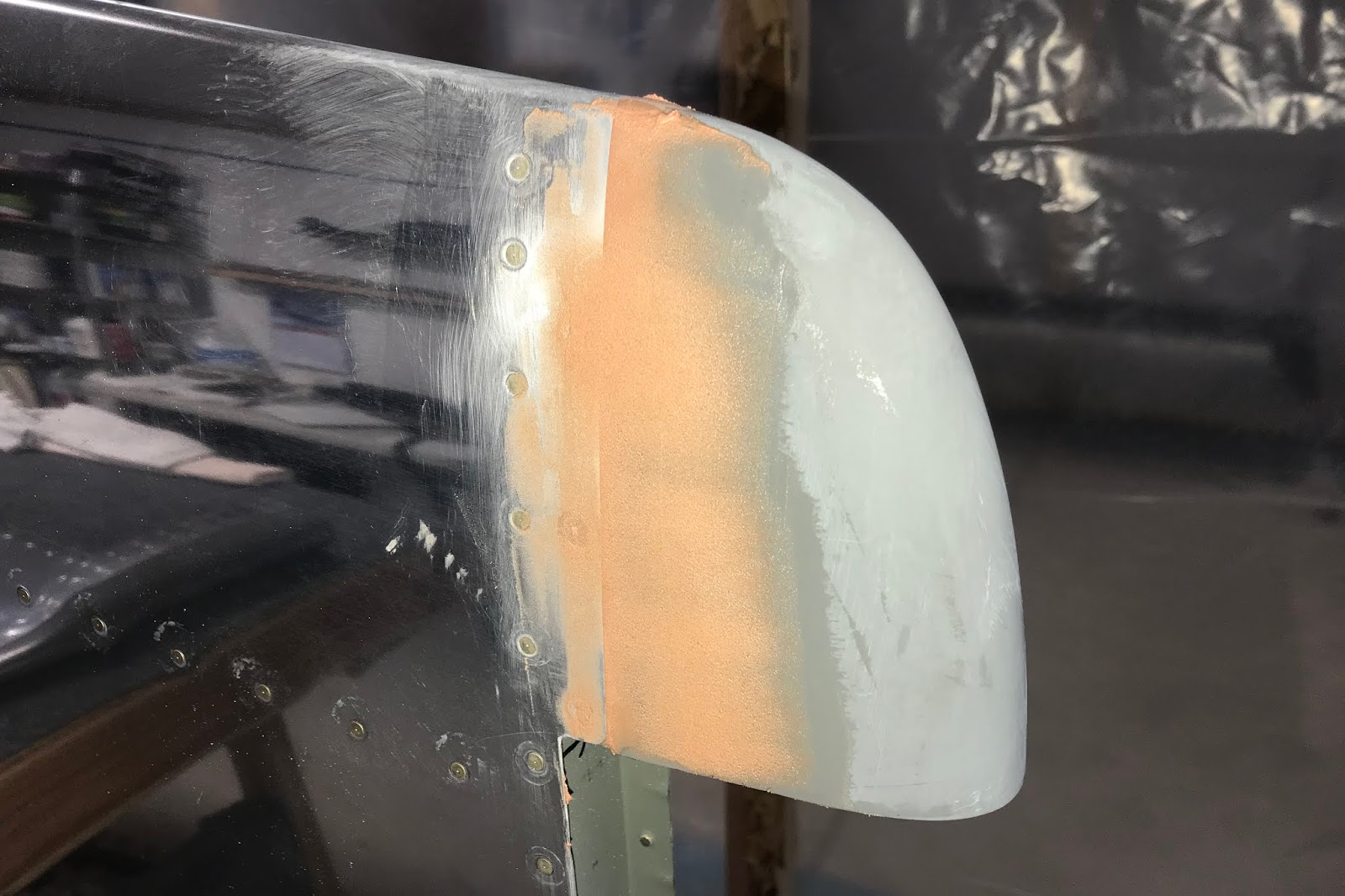
I had to wait out some bad weather before painting, so I got to work on other empennage parts. The horizontal stabilizer and elevators were moved from the garage into the main shop and inspected. To my dismay I discovered some damage to the trim tab hinge on the left elevator. I was able to straighten the hinge, but the stretched and straightened skin formed a dimple that will require some minor smoothing before paint. I started out by securing the horizontal stabilizer upside down on the C-frame table and then hanging the elevators, rigging them into proper trail using zip ties, rags and an anchor loop screwed into the table. The assembly had to be mounted upside down to accommodate the elevator horns. I began fitting the fiberglass tips to the horizontal stabilizer and elevator, keeping careful track of the left-right reversal on the upside down assembly. Some of the initial fitting work had been done previously. Plug ribs and forming ribs had been cut out of the foam-backed fiberglass panel I had from my Synergy Air training; some scuffing of the tips had been done and some holes match drilled. Some holes for the elevator tip rivets had been match drilled to #40; other holes had been final sized to #30 and dimpled. With the assembly correctly rigged on the table, the holes for the horizontal stabilizer tips still needed to be laid out and drilled. Doing some of this work upside down was a bit awkward, but necessary. With the tips carefully aligned and taped in place, all holes were drilled, upsized and dimpled to the correct sizes. The aftmost holes on each elevator tip needed to be riveted with smaller blind rivets because of tight clearances inside the tip. I found out that two holes I would have left #40 were drilled and dimpled to #30. I had to rethink and redo some things to make sure that both tips would look the same.


The rudder jig was modified for use with the elevators by adding a side/bottom platform on the wider end that would allow me to strap the elevator into the jig and upend the elevators into a vertical position to work on the tips with the elevator horn resting on a pad. It would have been nice to have two of these jigs so that both elevator tips could be worked on simultaneously, but it wasn't worth the hassle to build another jig. I just had to plan my work so that having to wait for filler to dry before swapping elevators wouldn't waste too much time.


When the weather cooperated I got to work on painting the rudder and vertical stabilizer. Both parts were inspected and some final touch up done. The rear spar of the vertical stabilizer was masked off. The rudder hinge bearing pockets were masked off and the rudder hung from the paint rack. The skins of the rudder and vertical stabilizer were prepped for paint using Scotchbrite pads on an elliptical sander and by hand, then cleaned thoroughly with alcohol and cleaning solvent. Then both parts were wash primed and primed. When the primer had dried, the rudder paint rack was rolled aside and enclosed in plastic. Then the olive drab base coat was sprayed onto the vertical stabilizer.


Once the base coat was dry, the rudder paint rack was unwrapped and rolled into position; the vertical stabilizer was moved aside and wrapped in plastic. The rudder would be one of the major masking challenges of the entire paint job because of the alternating red and white stripes. Like the American flag, it would comprise seven red and six white stripes of equal spacing. I also decided late in the design that I would add a blue stripe vertically along the rolled leading edge skin of the rudder between the counterweight and the rudder bottom. That would bring my original design closer to the usual training rudder scheme. First the entire rudder was sprayed with a white base coat. When that coat dried, the rudder was masked off for the red stripes. Determining the layout and spacing of the stripes on the oddly shaped rudder took some doing, but earlier experimentation had determined that the correct width of each stripe should be about 4.4" and I had figured out where and how they should be laid out. I used a large card stock template set the first guide line parallel to the front spar and a smaller handheld template to help keep the width consistent and accurate. The line layout was marked with small pieces of fine line tape, then the actual masking lines were run straight from piece to piece, checking it again with the template for accuracy. Once all the fine line taping was done, I masked off the six white stripes and the blue stripe, wiped down the red stripe areas with wiping solvent and sprayed the red stripes. Ideally, the masking should have been removed right after spraying, but being a novice painter I didn't want to risk damaging the red stripes. As a result the finished stripe edges weren't pristine, but I can live with them.


The next step was to mask off for the blue stripe. That was easier; I could just run my fine line tape along the tops of the red stripes and mask off the rest of the rudder. After spraying the blue line and unmasking, I noticed a couple spots where I hadn't quite masked to the red line; I would touch them up later by hand. I also noticed one small irregular spot along the trailing edge where I had somehow missed masking for the red stripes. I'd have to touch that up later, too.


Now it was time to mask and paint the tail numbers. The tail numbers were simulations of the serial numbers that appeared on WWII aircraft, which were six digits. I could have used my own serial number, but that's only five digits. I ended up using a sequence of numbers that has a secret and convoluted meaning for me, but would be meaningless to anyone else. (For the record, these digits cannot be rearranged into any PIN that I'll ever use, so don't waste your time.) Painting the numbers was also tricky because they had to be painted onto the rudder and vertical stabilizer simultaneously. I had to have two separate stencils made up because I needed to place a gap between the rudder numbers and the vertical stabilizer numbers, and because the numbers are always read left to right, the gaps were placed differently for each side of the rudder. I thought the stencil maker provided their own adhesive, but they didn't. I did some research on repositionable adhesives and bought some locally, saying a prayer that it wouldn't harm the fresh paint. I uncovered the vertical stabilizer and removed the masking from the rear spar. The rudder was removed from the paint rack and hung on the vertical stabilizer. The back of the stencils were sprayed with the adhesive and the stencils were placed onto the assembly and aligned. Then the rest of the assembly was carefully masked, the number areas were wiped down and sprayed with black paint, and the masking was removed. Again, the results were a little disappointing. The adhesive was less than ideal; it didn't seal the edges of the stencils like fine line tape would. I misted the paint on as carefully as I could, but the edges of the numbers were still sloppy because of the glue and loose edges. Oh well... they probably weren't pretty in 1943, either. In the future, I may use a roller to apply paint through stencils... might as well make it look really authentic.


With all the base coats done, the rudder was removed from the vertical stabilizer, rehung on the paint rack and the rudder hinge bearing pockets were remasked. The rear spar of the vertical stabilizer was remasked and the stabilizer recovered in plastic. I did the minor touch up to the red and white stripes where required on the rudder. Once they had dried, I wiped the rudder down with wiping solvent and sprayed it with two clear coats, then unbagged the vertical stabilizer and gave it two clear coats. These two components are the first airframe components to be essentially complete and ready to be installed on the airplane. On further examination, I'm not thrilled with the clear coat on the vertical stabilizer. It's pretty misty around the aft and bottom edges. I conferred with Sherwin-Williams and I might have to cut and buff it to get it smooth and even. I'll make that determination prior to final assembly. After curing for a while, the parts were moved into the garage and covered for storage.


Back to the horizontal stabilizer and elevators. The back side of the rivet holes in the fiberglass tips had to be reinforced with washers which I scuffed, tacked in place with five minute epoxy and reinforced with West Systems epoxy. The aft ends of horizontal stabilizer tips had to be closed with the plug ribs cut previously and the forming ribs had to be epoxied in place. The plans suggested using foam plugs to lay up fiberglass mat, then removing the foam. I needed to put the forming ribs in first and flox them in place before putting in the aft ribs, so I didn't bother removing the foam. I had laid up an oversize mat on the back side of each plug rib and epoxied them in place with flox around the outside edge of the rib.


In order to make it easier to install and finish the tips on the horizontal stabilizer, I wanted to place it on the stand I had made to hold it for painting. It needed to be very secure while I worked on the tips so I clamped the stand to the C-frame table with shelving brackets and wood screws. The elevators were removed from the horizontal stabilizer and it was placed on the stand; the upper spar was clamped down and the lower spar tied to the stand. I checked the fit of each tip and had to relieve some foam around the aftmost washer to allow the tip flanges to fit inside the skin properly. I mixed up a small batch of Aeropoxy Light and filled in the aft end of the plug rib, forming it into a slightly convex shape. It was easier to do this first fill before the tips were mounted. After it set up a bit, I prepped and cleaned the inside of the skin flanges and the outside of the tip flanges. I mixed up some Pro-Seal, applied it to the mating surfaces, fitted the tips to the stabilizer, clecoed them in place then secured them with blind rivets.


One small diversion from the empennage. With the high humidity we've had, I ended up changing the desiccant on the dehydrator plugs in the engine earlier than usual. One cylinder was effectively sealed, so only three of the four plugs needed fresh desiccant. I wish I didn't have to store this engine this long; it really needs to be run.


I began the work of filling and smoothing around the edges of the horizontal stabilizer tips. Small burrs raised around the mandrel holes of the blind rivets were ground down; the surfaces were prepped and Aeropoxy Light filler was applied. The left elevator was already in the jig so the left elevator tip was installed first. The mating surfaces for the elevator tips are a bit lumpy because of overlapping skins and built-in stresses. In order to get the best finished bonding shape of the Pro-Seal to the fiberglass tips, after assembly I clamped between the rivet holes with jaw clamps and clecoed the rivet holes. Then the clecos were removed one by one and replaced with blind rivets. The humidity was extending the drying time of the filler and the Pro-Seal; I had to wait two days before feeling confident enough to remove the clamps from the left elevator. Then I was able to swap the right elevator into the jig and attach the right tip in the same manner. As I was pulling the blind rivets on this assembly, an old problem reared its ugly, familiar head. The Surebonder rivet tool started breaking the mandrels long again; five out of eighteen broke long. I tried the usual fix of swapping the nose piece to the special one I ground down for this situation, but this time instead of breaking the mandrels properly, it just bit off an additional chunk of each mandrel. I documented the failure (again) and contacted Cleaveland Tool, informing them of the continuing problem and inquiring about whether they learned anything from the two tools I had returned to them. I was informed that due to my issues and the overall quality of the tool, they had stopped selling the Surebonder rivet tool. They currently did not sell a replacement and recommended a brand that was available on Amazon, or having their customers check other local sources. They did offer me a refund, but I declined. After all, I got three tools for the price of one, and got several years of work out of flawed tools because of their excellent support. I figure I got my money's worth. I was done pulling rivets for now, but I went ahead and ordered a replacement from Amazon. In the meantime, there was still lots of filling and finishing to do. I sanded down the first layer of filler around the horizontal stabilizer tips and applied the second.


In the course of working on the horizontal stabilizer, I had realized I would need another jig; one that would hold the stabilizer facing downward. That would make it much easier to finish the aft side of the tips, and it would allow me to hang the elevators to check the alignment. I wouldn't need them to be held in place because the counterweights would keep them in proper trail. So I made up a template that would fit around the leading edge at the middle rib line, got some scrap wood and started building. It didn't take very long, and was worth the effort. It was easy to mount the jig on the C-frame table so that I could flip the stabilizer back and forth if needed. The stabilizer fit in the jig very well, and I started using it right away to finish the back side of the tips.


I snipped off the long mandrels from the left elevator tip rivets and ground down the burrs on all the rivet mandrel holes. Then I cut two chunks out of my fiberglass panel, shaped them to fit the forward ends of the elevator counterweights and removed the foam backing. Returning to the stabilizer, I filled the notches I had carved around the aft washers with flox. Then I used the flox to glue the fiberglass cap onto the lead counterweights on the forward end of the tip, applying peel-ply to smooth it out. When the flox set up, I swapped the right elevator into the jig and repeated the process. The aft ends of the horizontal stabilizer tips were filed and sanded and a layer of Superfil was added to continue the smoothing of the shape. The cap on the forward end of the right elevator counterweight was trimmed, filed and shaped. Then some Aeropoxy Light was mixed and applied to the right elevator around all the edges of the tips for more shaping.


That brings us to the present. I had hoped to get the elevators swapped in the jig so I could trim and fill the left elevator, but the Aeropoxy Light takes a long time to set up in humid conditions and I didn't want to risk messing it up. Instead, I decided to get this blog done today, because the next two days will be filled with distractions. Tomorrow is EAA Chapter 194's first Young Eagles Rally and I'm going to help with that in the morning. Then I'm off to Windsor to participate in the Canadian Historical Aircraft Association's Flight Chops day. Steve Thorne will be meeting, greeting, flying and working on his RV-14; the flight crew will be giving rides and I'll be helping with ground crew duties, which will carry into the next day. So it's a good day to get this done. Or at least it was. It's now four minutes into tomorrow, which is now today... a very busy day... and I gotta get some sleep. More later, Stay Tuned!