Building progress in March started with some bad news: I learned that the 6AWG cable I had used for the main battery and starter circuits was inadequate for the task. I should have used heavier 2AWG cable. This sent me into a panic; the 6AWG cables were firmly secured underneath flooring that was now riveted in place. There was no way I was going to pull up those floors to get to that cable. After some careful thought and discussions with Jason at Aerotronics and other builders, I came up with a viable solution. I would install a new run of 2AWG cable from the battery to the master relay, forward through the firewall to the starter relay, and to the starter. The negative or ground circuit path would be shared by the 6AWG cable and the airframe with the addition of several extra ground straps. The existing 6AWG positive cable would be kept in place and used to bring power to the main buss. under the floors; the forward end cut and pulled back through the firewall, rerouted up the left gear tower, spliced and connected to provide the power for the main buss.

I ordered 2AWG cable and a selection of copper lugs, and while waiting for them to arrive I removed the baggage bulkhead, baggage shelf, pilot seat flooring and side panels. I also took care of some other wiring chores. The wiring for the alternator to the shunt and the alternator circuit breaker was completed.


Some of the undersized wiring was removed or detached and other tasks were done to prepare for the new cable. The lug on the forward end of the 6AWG positive cable was cut off; the cable was pulled back up into the gear tower and rerouted out the topmost lightening hole. It required a length to be spliced in to be able to reach the main buss breaker terminal.


I found a way to route the 2AWG positive cable forward underneath the left fuselage longeron. Once a few more holes were drilled in bulkheads and snap bushings or split conduit put in place, the cable and associated links were fabricated, routed and connected. Completing this fix was a huge relief.


Some other tasks were done during all the wiring. I got the large snap bushing installed in the bottom right engine baffle around the fuel line to completely stabilize it. I riveted together the right forward baffle and assembled the left one with clecos and fit to the engine. The sniffle valve was installed in the aftmost intake manifold drain and plumbed out to the rear of the cowling. I hung a mounting tab off the exhaust brace to support the drain tube. I also reviewed all my previous assembly instructions and notes to see what other details could be done at this stage. This research revealed that I had not yet safety wired the flap motor to the rod end bearing bolt, so that was done.


My goal was to get the firewall forward wiring done, complete all the connections behind the panel and route all necessary wires, cables and hoses out of the fuselage. Once all the connections were tested I could start thinking about putting on the top forward skin and working on the cowling. I spent a lot of time on studying instructions and plans, conferring with experts, researching and planning logistical solutions and drawing schematics to make sure I fully grasped all the aspects of this complex task. It had to be done right; having to undo and redo any of this work would be very difficult when the top forward fuselage and wing skins went on for good. I had to be certain I wasn't going to build myself into any corners. The drawings evolved as I refined my plan and corrected errors.


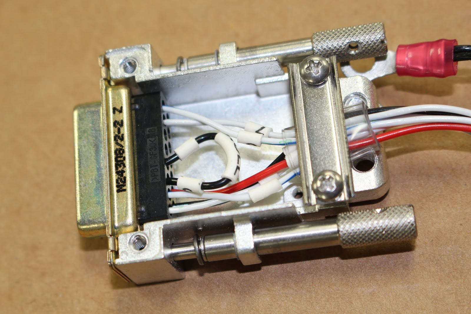
I set up a long shop table and other tables in a row and began laying out wiring for the wings; the runs had to start out about 15' long for initial bundling. This process also evolved as I realized that some labeled wires were actually redundant after changes to the panel as it was built. Some changes were discovered even after the wiring looms were assembled in heat shrink tubing, but I was able to re-purpose wires in the loom without having to cut open the bundles. Jason at Aerotronics suggested setting up a terminal block behind the panel for the wing wiring and I drew up the simple design illustrated above. But the more I thought about it, the less I wanted to bother with it. The idea was to make wing removal easier since I wasn't wiring up connectors at the wing root. But there would be no way to pull the wires out of the small snap bushings that the wires would be routed through. They would have to be cut anyway, so setting up the terminal block wasn't really necessary. The left/right sets of landing lights and taxi lights had to be combined to one pin each; same with the trios of left/right/tail nav lights and strobe lights. I wanted to use the smallest possible snap bushings to reduce the required the size of the required hole; the bushing ends were reamed out to the maximum possible diameter for optimal fit. Once the wires were combined, soldered and sealed with heat shrink tubing, the modified snap bushings were test fit over the wiring bundles to assure that they would fit. I had to disassemble the roll servo D-sub connector and remove the pins so that I'd be able to route it through bulkheads and through the fuselage side.


I practiced combining wires using solder sleeves; the results were ok, but I realized combining two and three wires to a single wire was better done soldering by hand. That would come later. It was time to start routing. I started with the roll servo bundle, which was taped to a fish wire and easily routed through existing holes in the right gear tower and spar box. I drilled a hole through the fuselage side just below the opening for the aileron push tube, deburred it and fed the wires through. Cutting a small amount out of the snap bushing allowed me to get it around the bundle and snapped into the fuselage hole, holding the bundle securely. I chose to route both wing bundles together through the right side of the spar box and up through the right gear tower. I would have to drill more holes in the spar box and gear tower; the aft holes were easy but access for drilling the forward holes was awkward. I made a platform out of plywood, a 2x4 and some spare carpeting that I could lie on while using the angle drill inside the fuselage. Once the holes were drilled and snap bushings were in place, I routed the paired cables through the spar box, into the right gear tower, up and out of the topmost lightening hole where most of the other wiring was already routed. Then I drilled holes in the two center floor ribs, routed the left wire bundle through them and installed the snap bushings using the same trim-to-fit method I used for the roll servo bundle. I coiled up the remaining length of the wing wiring looms and set them in the aft cockpit for the time being.


Next I worked on routing the pitot, angle of attack and static air tubing. The best location for routing the pitot and AOA tubes through the fuselage skin was underneath the cutout for the left aileron push/pull tube; I drilled two separate holes for those. The static tube was already routed forward all the way into the left gear tower but I wanted to group all three tubes together, so I pulled it out of the tower, drilled holes through the spar box and the left gear tower and routed the tubes all the way up through the gear tower and out the top of the fuselage. I wrapped the tubes with split conduit to prevent chafing in the tower and lower fuselage and secured everything with zip ties.


I had to order fittings to connect the tubes to the avionics and there were several different ways to approach the routing. I came up with some drawings, copied some photos of the fittings I wanted to use and photoshopped an illustration of the planned routing. I submitted them to Jason at Aerotronics for his approval, which he granted.


While I waited for the fittings to arrive from Stein Air, I worked on putting conduit in the wings. This would simplify final assembly, allowing me to complete the wings without the wires in place. I used PVC pipe for the conduits, which would be routed through lightening holes in the wing ribs in areas that would not interfere with any control tubes. The conduit supply at the local hardware store was somewhat limited, so I ended up using two different colors of PVC tubing; red for the right wing and white for the left. I needed to secure the conduits to every other rib with zip ties; this required drilling small holes in the ribs. Inspection covers were removed for access; drilling, deburring and zip tying was awkward in some areas. The right wing conduit was installed in one piece; the left was two pieces with a gap for the pitot heat wire routing.


With the conduit in place, I could determine the best location to route the wing wire looms out of the fuselage. Measurements were taken, holes were drilled, the wires were routed and snap bushings installed. The outside air temperature (OAT) probe cable had to be routed separately for installation in the left wing. The probe end of the cable is a permanent assembly, so the cable had to be pulled in from the outside. I measured the length of the probe cable and transferred the measurement to a long piece of electrical wire. After drilling the hole in the fuselage for the cable, I fished the electrical wire through the fuselage and spar box, up through the left gear tower and over to the OAT cable connector. Once I determined that the existing cable length on the OAT probe would work with my routing, I de-pinned the Molex connector, taped the cable to the fish wire and carefully pulled it through the fuselage and spar box, up through the gear tower and over to the other connector. The fish wire was removed, the connector re-pinned and the connection was made. Now the wiring from all the components that were connected to the avionics through the main P-1 connector were routed to the intended location behind the panel. Or at least that's what I thought. More on that later.


Now it was time to make all the necessary splices and connections before pinning the P-1 connector. I made short pigtail wires for combining the landing, taxi, nav and strobe wires, labeled them and crimped on the pins. I also made a wire stripping gauge indexed for 1/4" and 1/2" lengths. I put together a soldering station using a 2x4 and some clamps. The first connection I made was soldering the sync wires together and sealing the joint with heat shrink tubing. This was intended to be outside the P-1 connector, so I made this nice straight connection. Unfortunately, this would have to be redone later, as this assembly didn't bundle well.


In preparation for this assembly I reviewed my Aerotronics schematic, and discovered something missing. Mags? Oh yeah... I'm going to need P-leads from the mags, aren't I? Because the P-leads weren't supplied by either Barrett or Aerotronics, I hadn't noticed their absence until I examined the schematic. Darn... that meant another firewall penetration. Oh well. Ordered the P-leads from Aircraft Spruce and figured out my routing. Then got back to making connections... but first, some practice was in order. I made up a few test cables to simulate joining the nav and strobe wires and shields. When I was satisfied with my workmanship, I made the same connections with the actual aircraft wires. The sync wires were soldered and sealed; they would not require pins. The hot leads were soldered to their pigtails. The shields were soldered to ground wire extensions that would be combined later; all connections were sealed with heat shrink tubing.


When the P-leads arrived, I got to work installing them. Access was difficult with the mags installed, but I didn't want to remove them just to attach the wires. One ground screw was missing from one mag, so I took measurements and replaced both ground screws with Allen head cap screws, which would be easier to install. After a struggle, both P-leads were attached to the mags. A hole was drilled through the firewall, a snap bushing installed and the leads were routed through the firewall, into the right gear tower through existing holes and up into place.


I diverted from wiring to do the third round of preservation on the engine. I removed the dehydrator plugs, inspected the bores and fogged the cylinders using Sta-Bil fogging oil. While turning over the engine during the preservation process, I discovered that the front right baffle needed a notch to clear the ring gear, so I removed the baffle and notched it. The dessicant was changed and the dehydrator plugs and front right baffle were reinstalled.


The fittings had arrived from Stein Air, so installed the fittings in their ports on the GSU 25 and G5 units. I cut the pitot and static tubes to their initial length and attached the Y fittings. The AOA tube was cut to length and installed in the GSU 25 fitting. Extention pitot extension tubes were cut to length and connected to the Y fittings, the GSU 25 and the G5. The two Y fittings were joined together with a screw and acorn nut to stabilize the assembly.

Back to wiring. Using the spar box inserts from the fuselage stand and other scrap wood, I built two test platforms that would suspend the lighting and other components on each side of the fuselage for testing. Oh... and fuel sender wires... another forgotten item that wasn't supplied. I asked Jason about the correct gauge cable, and he sent some to me in short order. They were fabricated and routed into the fuselage. I crimped pins onto the remaining wires and carefully bundled everything so it would fit through the connector housing and lay in a good position. Then, finally, I began installing the pins into the P-1 connector. What's this? No starter relay wire? Oh bother. Fabricated; routed through existing holes; attached and pinned. When the pins were in place, the housing was screwed on and the housing's wire clamp carefully cinched in place. Then the P-1 connector was coupled and all the wire looms were bundled together and secured with zip ties as neatly as possible.


The only wiring left to do behind the panel was to combine the shield ground pigtails and pin them to the ground block; Jason mailed some female pins for the ground block and they hadn't arrived yet. So I got to work making temporary connections to the lighting, nav, strobe and pitot heat. I crimped the pins onto the wires coming out of the landing and taxi lights and inserted them into their Molex connectors; the sync wire from each would not be used in my aircraft. I couldn't put the female pins on until the cables were run through the wing conduits. I built a support bracket for the pitot mast, attached it to the left test platform and slipped the pitot/AOA tube assembly into place. The OAT probe was mounted to the left test platform. I made up a temporary ground path using bare copper wire and made all the necessary connections for testing on the left side, then did the same on the right side. I fabricated a bracket for the Suntail strobe, mounted it to the aft bulkhead flange and made the required connections. When the female ground block pins arrived, the remaining ground wires were combined and pinned; the pins were installed in the ground block and the ground block reattached to the ground plate mounted to the fuselage. Jason had recommended connecting the roll servo to avoid CAN bus errors during testing. I didn't really want to reassemble the D-sub connector knowing I'd have to de-pin and re-pin it later during final assembly, but I followed his advice. The D-sub connector was reassembled; the roll servo was attached to the right test platform and the roll servo loom connected. I also decided to make up a temporary support for the GA-35 GPS antenna puck and connect the coax antenna cable to the puck and the GSU 25 unit. All connections were now ready for testing.


I sent Jason more photos of the completed installation and conferred with him on the phone. He approved of the the overall appearance of my installation, and gave some good advice on how to proceed with testing. All the circuit breakers should be pulled before connecting the battery. Once the battery is connected, turn on the master and make sure the voltage flow is correct. Once this is established, reset each breaker in turn to test systems. Even though I know everything is correct, I was still terrified to make that first battery connection. There's a saying in avionics: whatever you do, don't let the magic smoke out. In other words, take care not to fry any very expensive components, which emit smoke when destroyed. I'm no electronics wizard; maybe I should hire an expert to do the testing. I voiced my worry to peers and they encouraged me to go ahead on my own. Ok then... it's time to do this. Give the battery one last top-off charge, connect the two 6AWG ground cables to the negative battery terminal and connect the positive 2AWG pigtail to the positive battery terminal. Wait a minute... the long 6AWG cable that's secured under the floor and through the firewall won't reach the battery. It's two inches short now. I know I test fit it before... how the hell did that happen?! Doesn't matter... it's short now. I had to borrow Leo Knowlden's hydraulic crimper again, along with a couple 2AWG copper lugs fabricate another pigtail to connect the cables to the battery terminal. That's ok; just a little more work, and the finished product looks like I meant to do that. I also included the charging pigtail before crossing my fingers, saying a little prayer and connecting the positive cable. No magic smoke. All's well, so far.


The first thing I tested was the interior map light. Push in the breaker, turn on the master and turn on the rheostat switch. Hey, look at that... it works! Push the nav/strobe breaker in and test the switch. They work; so does the strobe. Pitot heat breaker in; switch on; it works. Push in the landing and taxi light breakers; try the switches... no joy. Flap breaker in; test flaps switch; inop. Fuel boost pump breaker in; test; inop. USB ports and 12 volt accessory plug breakers in; connect accessories; both work. Ok... time to turn everything off, pull all breakers, take a break and do some research.


Comparing my test notes revealed that most inoperative items were also controlled by the GAD 27 interface module. I assumed that they probably wouldn't work until more circuit breakers were pushed in, so I pushed in all the breakers and performed more tests. Now the G3X and G5 lit up with the master on. No magic smoke. The landing and taxi lights worked, as well as the pulse feature for the landing lights. The flaps worked, but the direction of the switch was reversed. Upon shutdown, the battery backup for the G5 did its job. The only puzzling exception was the fuel boost pump; that should have worked. A second test caused the breaker to pop. I checked the voltage to the pump motor wires with the switch turned on and it was getting the right amount of power. That confirmed circuit continuity, so it wasn't a wiring issue; that also explained why the breaker popped. The fuel boost pump installation instructions advised against operating the pump dry; it should be flushed and filled before use. Maybe the pump is preserved prior to shipment and is sticking; without being able to turn, the motor popped the breaker. Or perhaps there's some sort of fail-safe mechanism that won't let the motor run if the pump is dry. Another call to Jason confirmed my diagnoses; even though the lights and flaps had their own circuit breakers, the other avionics had to have their breakers in to power up the GAD 27. I asked if the flap actuation could be reversed in a configuration setting during calibration. He said no; I'd either have to switch the wires or rotate the switch 180 degrees. We discussed how to check other firewall-forward circuits. Most could wait until after the first engine start, but I can check the starter relay by disconnecting the lead to the starter, turning the key on to "start" and listen for the clunk of the starter relay activating. I should not activate the starter itself without a load. He also confirmed that the avionics switch on my aircraft only sends power to set of avionics circuit breakers on the left side of my panel labeled "Avionics Bus". He wasn't sure about the fuel boost pump issue; I'll have to confirm that myself.


That's the status of my building progress as of this writing. I created short video of the testing experience and posted it to my YouTube channel; here's a link:
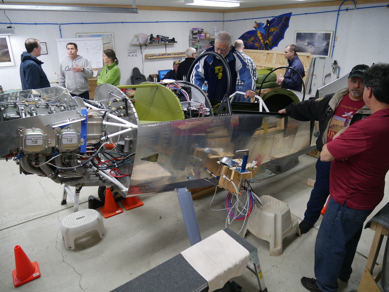
The last actual work performed was on April 26 and I've had a lot of distractions since then; mostly good. My EAA Chapter 113 wanted to have the May homebuilders meeting be a road trip north to visit my shop and Leo Knowlden's shop, so I spent some time getting ready by rearranging and cleaning. The visit went well, and the oatmeal butterscotch cookies Amy made were a big hit. Shunsuke Shibata took photos and I captured time lapse video at both locations. I'll share my prep photos, Shunsuke's photos and a link to the time lapse video here:


A few other significant changes occurred. Long-time readers of this blog will recall that in order to start this build a year earlier than planned, I sold my beloved 2008 Mustang convertible. In 2016 I bought a Ford F-250 pickup; the same one I used to bring the engine back from Tulsa after the Barrett engine build (see Barrettrip 2018 Movie; also on my YouTube channel). I had always intended to trade that pickup in for another Mustang convertible after the airplane was at the hangar. But I decided I couldn't wait any longer. I found the Mustang that I wanted at Kistler Ford in Toledo. Yes, this could be considered a plug, because it was the best dealership experience I've ever had. I got a fair trade-in value, a great deal on a 2014 Mustang GT convertible (one owner; low miles; excellent condition) and cash in my pocket. So I'm a Mustang guy again, and very happy about it.


Of course I would rather not drive the Mustang at all in the winter, and I don't want to put a trailer hitch on it. So I started looking for a winter beater with 4 wheel drive and a decent towing capacity that could be bought for the cash provided by the Mustang deal. Buying a cheap used car is never fun, but after some effort I found something that fit the bill: a 2003 GMC Yukon XL 1500. It's a work in progress; a few things need fixing and the interior is somewhat gross. But it runs really well and has good bones, so I'm happy.

Now that I've got the Mustang, I'm trying to sell my 2015 Honda Gold Wing f6b. I love it, but have to be honest about how much I'll be riding it... as well as how much I should be riding a bike this big on Michigan roads with Michigan traffic. I have an ad placed in Cycle Trader; let me know if you're interested... I'll make you a sweet deal.

Ok, back to airplanes. I haven't mentioned any flying adventures in this blog since my entry about getting Pitts training from Budd Davisson last November. There have been quite a few since then. The day after Christmas, I took Amy flying for the first time in 20 years. It was a perfect day for it; cold, calm and clear. We took off from PTK in the Crosswinds Cessna 172SP just before sunrise and headed east. We landed at Romeo (D98) and taxied back just in time to watch the sun rise, then took off for a touch-and-go at Lapeer (D95) before heading back to PTK for some pattern work. The air was like glass; I could do no wrong. It was a great Christmas present for us both.


The very next day I went over to Windsor to meet up with Steve Thorne of Flight Chops fame and got a chance to ride in the CH2A Harvard with him during a recurrency flight. I was actually the first passenger he ever flew in the Harvard, but since I was a fellow CH2A pilot it didn't really count. He had made arrangements to fly another CH2A recruit, so we did two quick pattern circuits before I swapped seats with Brian and Steve took him up for some flying before coming back for his third landing. It was another spectacular winter afternoon for flying, with great lighting and conditions for photography. Afterward we headed out for dinner at a local steakhouse and talked awhile before heading home. I took a lot of photos and some video, and Steve used some of my footage in the video he posted on the event. Rather than posting photos, I'll share a link to Steve's video that includes me as well as some of my photos and video in the content. I'm truly honored.
Flight Chops Video: Test Prep study: Struggle is Real
Another great CH2A opportunity presented itself on January 4 when I went over for a breakfast meeting and was fortunate enough to ride along for a formation practice flight. David Carrick flew lead in the Harvard; I rode along with Aaron Barnhard in the Chipmunk and the other wingman was none other than legendary RCAF pilot Ron Holden flying a Titan P-51. Again, I felt honored to get the chance to be part of this flight. I took some photos and some video, but also took some time to put the camera down and just savor the moments. "Just so cool" doesn't even begin to describe it... but this video might give you a glimpse of what it was like:
CH2A Formation 190105


Since then I've kept current with a few more flights and some sim work. A couple days ago I got another treat when hangar neighbor and friend Mike Hull invited me along for a flight in his Cirrus SR22 over to Coldwater (OEB) to meet some of his friends for lunch. He made it an aircraft familiarization flight on the outbound leg, and I got to watch him fly an IFR flight plan on the return leg. More good times, to be sure.


I know this has been another very long entry, but now I feel completely caught up. I look forward to the next entry and lots more progress. But now I simply must get back to work on the airplane. As always, Stay Tuned!