I ended last year with the statement "Next year will blow your mind". Honestly folks... I had no idea... as I write this we're in the middle of the COVID-19 pandemic, and the world has probably changed forever. But I'm fortunate that my life hasn't changed all that much yet; still keeping my head down and building my airplane, slow but steady. This is the 91st day of this year, and so far I've only skipped 9 days of work. Many days have been four hours or less because of the nature of fiberglass work (apply, cure, sand, repeat), but I've kept the ball rolling... so much so that I haven't wanted to stop and update this blog. There's a lot of ground to cover here, and I may not go into the depth of detail that I usually do because that would take a month to write, and I can't spare another month. But maybe with the help of some links I can get you caught up in a timely manner
January was mostly baffle work, and that included a major setback. The instructions mentioned that some steps should not be completed until the cowling is fitted. For example, the best location for the oil cooler opening is determined by how low and close the cowl comes to the left rear corner of the baffles. But many parts are affected by those parameters, and it can become a major roadblock for first time builders. So when I was working on the baffles a year ago I did some research and took what I thought was an educated guess on where the oil cooler should be mounted on an RV-8. Based on that information I cut, drilled and shaped many parts of the left side and aft baffles, including some extra bracing that isn't included in the plans or kit, but experience has shown are definitely required to reinforce the area. Some of these parts were riveted together to make it easier to pre-assemble components as needed. With the cowling coming together, it was time to trim the baffles to fit under the top cowl. As the trimming progressed it became painfully obvious that there was no way I would get the oil cooler to fit under the top cowl where it was currently mounted.


I briefly toyed with the idea of modifying the cowl to fit around the oil cooler, and laid out relief areas that would need to be cut out. But I also reviewed other builder solutions and sought advice, and that led me to make the decision to relocate the oil cooler downward and inward enough to fit. New stock parts were ordered from Van's and the custom reinforcement parts were remade from scratch. Only a few of the parts I had made before could be reused, and they required extensive modification. I took advantage of the rework to improve the mounting of the oil cooler and to also make it possible to separate the aft and side baffles without having to drill out rivets, making any future disassembly much easier. These changes added about a month's worth of extra effort, but it was worth it. Once I was satisfied they all fit, the components were riveted together where required and attached to the engine.


Now that the oil cooler/left aft baffle assembly was fitted, I could trim the right side to fit. This went far more smoothly, of course. When the parts were trimmed enough to fit under the cowl without contact, I used the paperclip method of determining my actual gaps. I made up a gap gauge that helped me layout final cut lines that would leave me with the required 3/8" minimum gap. The gap on the right aft corner is still a little bit tighter than 3/8", but I'll wait until after engine runs to determine if this is an issue that will need to be addressed. At this point the aft baffles were permanently installed and sealed, including Permatex Ultra Black applied to the bottom baffle tabs that wrap around the bottom of the cylinder fins.


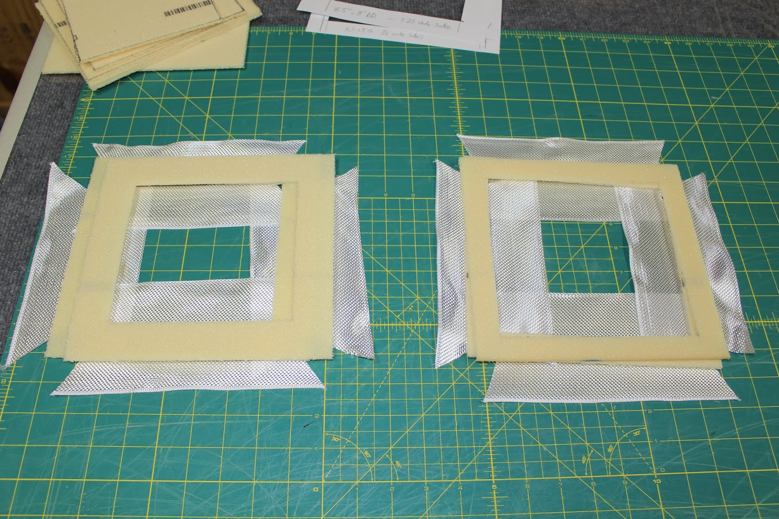
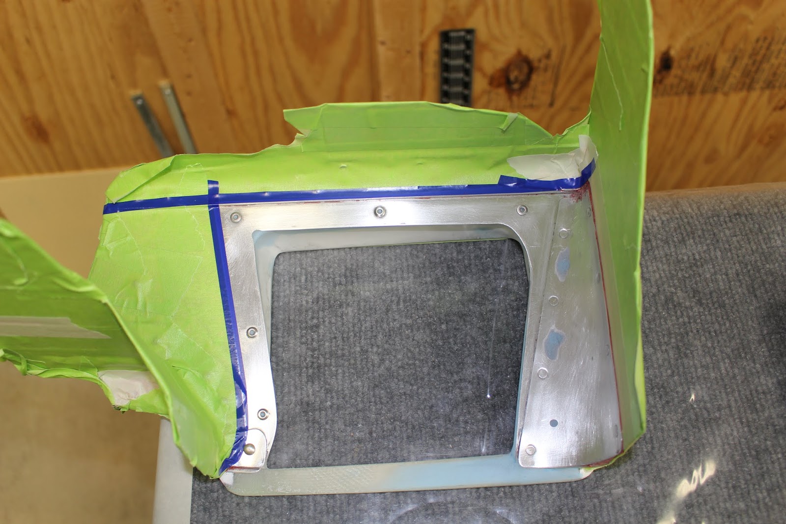
Some other items that were taken care of were making up an oil cooler blocking plate assembly for the aft of the oil cooler, and fabricating blast tube assemblies with screened inlets for cooling the mags. There is some debate as to whether putting a blocking plate on the back side of the oil cooler is effective, but I didn't want the additional complication of using shutters on the front. I did make up a front blocking plate that can be bolted on, using one of the oil cooler brace bolts. It will be stored and used if needed.


In the course of fitting the blast tubes, I discovered an error I had made earlier. I noticed a plastic plug in the oil filter mount that hadn't been used or plugged yet. I conferred with Allen Barrett via text and photos and he informed me that the oil temp sensor should have been screwed into that hole. Following Van's general instructions for an IO-360 engine, I had installed the oil temp sensor in an adjacent hole in the accessory case. Normally this shouldn't have been a big deal... but the sensor was already wired and the wires bundled. To make things more complicated, there was some initial confusion about the threads of each hole. Allen thought the case threads were NPT; if so, the hole would be easily plugged and sealed. But they turned out to be straight threads; that would require a cap that would have to be safety wired. I ordered an aluminum cap from Pegasus Auto Racing that would work, but I'd have to drill it for safety wire. When I removed the plastic cap, there was some weird green gummy stuff in the hole that had me alarmed. What was THAT doing in my engine?! Allen had no idea what it could be or how to remove it, but I gingerly removed it with a part hanging wire. It turned out to be green masking tape! We surmised that when Curt was pickling the engine, the plugs he had available wouldn't fit that hole precisely so he shimmed the plug with the green masking tape. When I removed the plug, the tape stayed in place and residual oil had soaked it into a gummy lump. But it came out cleanly in one piece, which was a huge relief. The oil temp sensor was disconnected and relocated in the correct hole, reusing the original crush washer per Allen's instructions. I had tried to determine the clocking of the cap with a fresh washer to determine the best location for drilling the hole for the safety wire, which in itself was a pain. But when the cap was actually installed, it became obvious that my clocking was inaccurate; I had to drill another hole before the cap could be cinched down and safety wired to the oil temp sensor, which turned out to be easier than expected. The sensor was reconnected, the wires were bundled again and everything that had been moved out of the way was put back in place. It felt good to wrap up that episode.


As February began I allowed myself a minor diversion. I ordered a wheel wrench kit from Van's and assembled it. This will be an important part of the toolbox I plan to keep in the airplane. I didn't make it pretty, but I made it durable and coated it with a light coating of oil to keep corrosion at bay.


The front baffle work continued, trimming the pieces to final shapes and hand-forming the custom gussets and joins that are part of the assembly. Some more cowling work was done, joining the inlet ducts to the top cowl with epoxy resin to assure that the front baffles and cowl intakes would come together as they should. A blast tube for the alternator was cut and an associated hole drilled in the right inlet ramp. It gradually came together well.


When I was happy with the way the front baffles integrated with the cowls, I dug out the parts, plans and instructions for the induction snorkel. Van's cowlings come in two configurations, depending on the type of induction the engine uses. Engines with vertical induction use a bottom cowl with a scoop that feeds an air cleaner box attached to the carburetor or a fuel injection servo, also known as a fuel control. Engines with horizontal induction use a smooth bottom cowl; the air is drawn in through an air filter mounted on the intake ramp of the left cowl inlet and directed to the fuel control through a fiberglass snorkel. Each design has their advantages and drawbacks. One reason many builders choose horizontal induction (myself included) is because of the graceful lines of the bottom cowl without the scoop bulge. Van's snorkel design is pretty good, but it's one of those pieces that usually requires at least a little customization by the builder based on engine configuration, equipment, front baffle design and other factors. Some builders practically bolt it on; some scrap it and make their own snorkels from scratch. But most modify the stock snorkel to make it work for them; one well-known VAF moderator (callsign "Scroll") coined the term "FrankenSnorkel" for this approach. When I reviewed Van's snorkel assembly instructions (a separate document from the standard instructions), I knew I was in trouble when I read "Note: do not finish trimming the left intake ramp before beginning this assembly"... right after completing the fabrication of all my forward baffle components. Funny... there was no such warning in the standard instructions I had been following up to that point. Holding the air filter up to the underside to my beautifully cut-and-fit left ramp components, I knew there was no way to assemble the air intake their way unless I scrapped every one of the many assembled stock and custom baffle parts associated with the left front corner of the engine and did it all over again. Having already gone through all that with the left aft corner of the engine, I wasn't keen on that idea... and the more I reviewed the instructions and drawings, the less I liked the stock design. That left no other option than to create Son of Frankensnorkel. My idea was to use blind rivets and Pro Seal to bond a custom composite intake to underside of the left ramp that would channel air to a removable air filter tray. The tray would be sandwiched between fiberglass flanges on the bottom of the intake and top of the snorkel. Dry gaskets would be used on both snorkel flanges; the air filter sides would make the seal to the intake flange. Four bolts would pass from the bottom of the snorkel flange upwards through vertical holes in the sides of the intake tray and tighten into nut plates attached to the upper side of the intake's bottom flange. The upside down bolts would be kept secure by safety wiring the bolt heads together to prevent any chance of their becoming loose. It seemed like a good plan. Initial examination showed it could be made to fit in the available space; I could leave my metalwork as fabricated, cut an opening that would work around it and design the intake to fit the opening. The removable air filter tray meant that I wouldn't have to remove the entire snorkel to service the air filter; just cut the safety wire, remove four bolts and pull the tray out. To reassemble, just replace bolts, snug up and rewire. If other guys could do it, so could I. There were a few more mods required to clear the starter, but those could be simple cut and patch jobs. Sure, I could do it... I just had no idea that it would feel like I wandered off course into a deep, dark, impenetrable forest where I knew which to go... I just couldn't see where I was going more than a couple steps ahead. Believe me, it got spooky... and it felt like I was leaving the airplane behind. But I knew I was going in the right direction, despite taking a few incorrect routes and having to redirect my path. When I was close to finishing, I could see the light through the trees, and when I burst into the clear, I was in a slightly different place than I expected to be... but I had traveled the necessary distance to clear the forest and get back on the charted path. It would take a book to describe the journey in detail, and I don't want to write much more of a book than I already have here. But I did document it in a three-page thread I created on the VAF forum. I'll share a long string of photos here (mostly development photos that aren't in the VAF thread) and include the link so you can read that account, see the best photos and hopefully get a pretty good idea of what I went through.


You'll note that there is no alternate air door provided on the snorkel. I discussed this with many builders and tech counselors, including my DAR. I don't know percentages; most builders probably install alternate air doors, but there are many builders that do not install any alternate air system. To me, it all comes down to my mission. If I were planning to fly IFR or intended to plan flights that might require flying through weather that could change rapidly into icing conditions, I would definitely install it. But one of my most important personal limits as a pilot is that, because I intend all my flying to be purely recreational, I will never put myself in a position to be under time constraints. Therefore I will only fly when conditions are right and safe for my intended mission. This is a VFR airplane, and I intent to only fly it in VFR conditions. That means that I will never fly this aircraft in any conditions that could lead to icing, which is the primary reason to have to use alternate air. I do have the alternate air door kit and I know where and how I would install it should I choose to do so in the future. But it is not installed now, so I'll just have to make sure I never fly in conditions where I might need it.
When the snorkel approached completion and I was certain the baffles would need no more modification, Permatex Ultra Black was applied to the lower baffle tabs and the front baffle assemblies were attached to the engine, torqued and sealed so the Frankensnorkel could be installed, sealed and safety wired. The alternator was adjusted to the correct belt tension and the mounting bolts were tightened and safety wired. The prop governor oil hose was attached, torqued and sealed. The alternator blast tube and screen were sealed to the right inlet ramp and secured with safety wire. The stainless steel tension rods that pull the bottom baffle tabs together had been cut to length earlier; I had also made dummy rods out of aluminum rod to experiment with fabrication before threading and bending the stainless steel rods. Installing them was trickier than expected. I knew access would be difficult on a completely plumbed, wired and connected engine, but the way the Barrett-built Superior IO-360 was assembled, the fuel injection plumbing was right across the intended path of the rods. It took some creative bending to come up with a solution, but I was happy with the fit. Lots of room around the injection plumbing, even under tension. Still, I played it safe by slipping the anti-chafe plastic tubing supplied by Van's over the areas that were anywhere close to the injection plumbing or the bottom inner baffle plates assembled onto the engine at Barrett. The baffle metalwork is complete and installed now. There will be additional sealing to be done around some areas of the cases in the future, and once the cowling is complete I will attach the baffle fabric to the top of the metal baffles and around the inlets. But what's on there now should be there to stay. Oh, and by the way... you'll see a photo of a rag taped to the front right corner of the baffles with green tape. When you're working on getting those tension rods installed, it's a good idea to put padding on the lower front corner of the baffles before you cut your forehead and/or gouge the top of your head on that corner. Trust me... it's not good to have to keep working while injured and angry.


By this time it was mid-March and this blog was overdue... but I had to do our taxes first and I also wanted to get to a good stopping point before composing this entry. A few minor jobs were addressed; the red cube (fuel flow transducer) was wrapped in insulating tape, as were the mixture and throttle cables... at least partially. Experts suggest putting firesleeves around the cables; some say they never needed it; others have had cables start to bind after prolonged exposure to the heat below the engine. I really didn't want to face disconnecting those cables after what I went through installing them, so I thought I'd try wrapping them in the insulating tape. I don't know if it will hold up, but I'll keep a close eye on it and see. Some of the tape edges susceptible to fraying were sealed with hi-temp gasket maker. While I was at it, I sealed most of the firewall penetrations, including the perimeter... or at least I tried. Access to the upper firewall edges is quite awkward with the fuselage held level, and I think there may still be gaps. When I complete the last of the baffle sealing I will go over all the firewall areas to make sure they're good.


It was time to switch back to cowling work, finalizing fit and finish of both halves. I had modified the air filter tray and snorkel/intake flanges as much as I dared to get clearance for the left inlet of the bottom cowl, and I had gotten pretty close. I had to sand away just a little bit of the inner edge of the inlet to make it possible for the bottom cowl to clear the air filter tray and flanges and hang in the correct place on the hinges. I clecoed the horizontal rows of Skybolt flanges back onto the bottom cowl and started refining the fit of the top cowl, grinding away some of the composite sandwich that interfered with a few of the forward flanges. I ground some holes through in a couple of spots, but those would be easy to fix. When it looked like the top cowl was sitting where it should, I removed the entire cowling and built a table jig to support the bottom cowl in a level attitude. Securing the bottom cowl to the jig, I taped the Skybolt cleco inserts to the flanges, placed the top cowl on the bottom in correct alignment and match-drilled #30 pilot holes for all 18 of the the horizontal Skybolt flanges. Reinstalling the cowling on the fuselage, I clecoed the top cowl in place and checked the fit, which looked good so far.


The top cowl was removed and work started on the oil door. The door itself is shipped is an oversize piece with molded-in guide lines for final trimming. Initial cuts were done with a band saw and then the edges were sanded to the guide lines. It was well-molded part; the curve matched the inset on the top cowl precisely and sanding to the cut lines created an accurate fit. I wanted to use two of my leftover Skybolt flanges as corner latches for the door. Measurements were made and the flanges were cut to the optimal shape. Rivet holes were laid out and drilled through the flanges, then the flanges were shaped by hand to conform to the curve of the surface of the bottom corners of the oil door inset in the top cowl. The rivet hole layout was transferred to the inset, then the rivet holes were match drilled through the top cowl; these would be enlarged up to 15/32" with a Unibit for initial sizing. The flanges were clecoed in place on the exterior of the insert and a flange insert was used to drill #30 pilot holes through the top cowl for the receptacles that would be riveted to the flanges. With the rivet and pilot holes drilled and the outline of the flanges marked on the door inset, the layout of the opening was drawn. Corner holes were drilled; the opening was cut out with a Dremel diamond wheel and the edges sanded straight and smooth. The flanges were clecoed to their correct locations on the inside of the top cowl and checked for fit; all was good.


Before continuing work on the oil door, I wanted to figure out how best to drill the pilot holes for the firewall flanges. Six of the cleco inserts were borrowed from the horizontal rows and taped to selected flanges along the firewall. I thought it might be possible to match drill at least a few of the pilot holes by reaching through the oil door opening, but with the top cowl in place that proved to be impossible Instead, magnetic barrels and magnetic ball bearings were used to mark the outside edge of the top cowl for pilot holes; one on each bottom corner and four staggered along the top. This was for pre-alignment purposes only; fiberglass must be laid along the inside of the top cowl's aft edge before final drilling is done. But it was looking good so far.


Returning the top cowl to the C-frame table, I started working on some of the required fiberglass fabrication on the interior. I had to make a composite pad for the cowl side of the oil door hinge to sit on; fortunately a piece of scrap from fabricating the Frankensnorkel turned out to be perfect for the application. It was bonded with epoxy; the edges were filleted with flox and the pad was clamped in place to cure. Rivet/cleco holes were laid out along each strap of the oil door hinge and drilled. With the oil door centered on the inset and taped to the top cowl, the location of the hinge straps on the cowl and door were finalized, laid out. The pilot holes in the cowl side hinge strap were match drilled through the pad and top cowl. The hinge was assembled and clecoed to the boss. Left as is, the oil door is flimsy enough to flex with air pressure during flight; with a single latch point in the center, it's not uncommon for an unmodified oil door to pop open in flight. Some have even been ripped off. It's good practice to reinforce the body of the door and hold it closed at the corners with substantial latches such as the Skybolt fasteners. The cut out area of the insert makes a good base for reinforcement due to its size, shape and curvature. To make it even more substantial, I cut out a piece of thin foam board to cover the area of the cutout below the oil door hinge strap, and a matching mat of fiberglass to cap it. This layup really cried out to be vacuum bagged during curing, but I don't have the required equipment or expertise and really didn't want to take the extra time and expense of figuring out how to do all that for just one part. Using some scrap core foam, I made a form table that would allow the assembled composite to lay flat and as level as possible. The parts were prepped, epoxy was applied and the layup assembled. Using a weird combination of plastic sheet, peel ply, a sanding sponge, more foam board and a paint stir stick, I managed to clamp the parts together gently, massaging the alignment carefully (and repeatedly) until the layup looked good and stable. I added some microballoons to the leftover epoxy and applied the resultant slurry along the edges of the inlet ducts. The next day revealed that, unlike my earlier attempts at multi-layered layups for the air filter tray, this time everything cured up straight and true. I mixed up some more microballoon slurry and encased the composite reinforcement with it, which would produce smoother surfaces and edges. Adding some flox to the slurry made a good mix for patching the holes I had ground through the top cowl along the relieved areas of the flange notches.


The basic structure of the oil door was complete. With the assembled hinge clecoed to the top cowl pad, the fit was checked. I knew in advance that the oil door hinge strap wouldn't lay flat on the door; it rested on the front edge and raised up aftward. This could have been fixed two ways: bend the hinge strap to conform, or build up a composite boss that would allow the strap to lay flat. I didn't like the possibility of misalignment of the hinge pin ears caused by deforming the strap; the boss seemed like the better idea. Packing tape was wrapped around the oil door strap to act as a mold release; the perimeter of the oil door opening was also masked with packing tape. The oil door was taped in place in the top cowl inset; electrical tape was used to mask the inside edges of the oil door . I mixed up a batch of flox, applied it to the required area and carefully pushed the wrapped hinge strap into the flox, displacing and forming it into the required shape. With a little bit of added flox and some gentle wiggling of the strap, a decent boss was formed and left to cure. The next day, the parts were separated and the boss looked excellent. Rivet holes were match drilled through the door strap, the boss and the door; the outside hole edges were countersunk for flush rivets. Rivets were placed through the rivet holes for the Skybolt flanges and taped in place; the flanges were placed over the rivets on the inside and taped down to the inside of the top cowl with cleco inserts in place. The hinge was assembled with the spring in place and clecoed to the cowl pad and door boss. With #30 clecos to hold the oil door shut, the door was braced by hand as the clecos were removed. Checking the actuation of the sprung hinge and the door travel showed that everything worked as designed.


I was confident that it was time to rivet the receptacles to the flanges and insert grommets and studs into the oil door. But when I laid a receptacle onto one of the flanges, I realized I had made another classic error. I had laid out the mounting rivet holes on the flanges without taking into account the size and shape of the receptacles that had to be riveted to the flanges before the flanges could be riveted to the top cowl. The cage plate on the bottom of the receptacle partially occluded two of the three mounting rivet holes on each flange. I only had one flange left, so I couldn't make two new ones; I wasn't going to order just one more flange and wait for it to arrive. So I notched the receptacles just enough to make enough clearance to rivet the flanges; they would also be glued down with Pro Seal, so the rivet sets didn't need to be perfect. The receptacles were then riveted to the flanges. Several more steps had to be taken before attaching the flanges to the top cowl permanently. The receptacle holes in the top cowl were enlarged to match the holes in the flange. More slurry was mixed and added around the perimeter of the door hinge strap boss and the cowl strap pad. The holes in the top cowl hinge strap and pad were drilled out to accommodate 8-32 flat head stainless steel screws. The outside hole edges were machine countersunk, first with a fiberglass grinding countersink bit, then a standard wood countersink bit because of the standard angle on the screws. One countersink dug into the composite layer and was a bit oversized, so I mixed up some five minute epoxy and added it to all four countersunk areas, then set the screws in place to form it to the correct shape. The result wasn't perfect, but it would work. Finally, the cleco holes in the oil door bottom corners had to be drilled out to 15/32" to accept the grommets and studs. Pro Seal was mixed and applied to the mating areas on the top cowl; the flanges were put into place over the rivets and the rivets squeezed to complete assembly. The grommets were installed temporarily to check function, then removed so that the back side of the oil door could be sprayed with filler/primer, smoothed, sanded and painted with VHT white paint. Custom rivets were cut to different lengths to accommodate the varying thickness of the boss. When the paint was dry, Pro Seal was applied to the boss and the door hinge strap was riveted in place.


After the Pro Seal under the door hinge began to set up, the cowl hinge strap was cinched down with temporary nuts and the hinge was reassembled with the spring in place. The grommets and studs were reinserted into the oil door and held in place with temporary O-rings. Now the receptacles could be set to the correct depth. The studs were engaged with the receptacle and rotated clockwise until the door was pulled down to a snug closed position. The locking clip pins were removed and the receptacles were rotated just enough for the locking clips to engage one of the slots in the receptacles, preventing any further rotation in either direction. Now the Skybolt fasteners are fully functioning, and so is the oil door hinge. I couldn't resist taping the inserts back onto the horizontal flanges on the bottom cowl, putting the top cowl in place with clecos and practicing the operation of the oil door as if I was doing a preflight. I even captured the process on video, made a one-minute movie and posted it on my YouTube channel. Click on the link below the photos to see it.


And that, finally, brings us up to date. And by now, it's no longer the 91st day of the year. It's 4:40 a.m. on the 92nd day of the year. As usual, this was longer than I wanted it to be, but at least most of that length was taken up with photos. I plan on getting some sleep, waking up sometime this afternoon, and getting back to work on the plane. Nothing better to do; can't fly because Crosswinds Aviation is closed till the end of April. Can't go to Windsor because the border is closed to non-essential personnel. I can drive the Mustang around, as long as I don't get out of it (except to fill the tank). Shouldn't be around anyone but Amy... but that sounds ok to me. I'm actually pretty lucky; aside from the overriding stress of having life in America upended, my life hasn't changed too much. Here's hoping we can all get through this alive and healthy. My prayers and hopes go out to all of you. Don't worry too much about me... I think we're going to be ok here. Stay tuned.