Fun summer distractions continued through August and into September, and hundreds of additional photos were taken. Woodward Dream Cruise, Roadkill gatherings, drumming gigs, ground crew duty for the EAA-sponsored Ford Trimotor annual visit to PTK, and the Yankee Air Museum's Thunder Over Michigan Airshow at Willow Run where I got my first ride in their B-25 Yankee Warrior.
I posted a YouTube video of a ride in the Trimotor; here are some photos I used as alternate title pages:


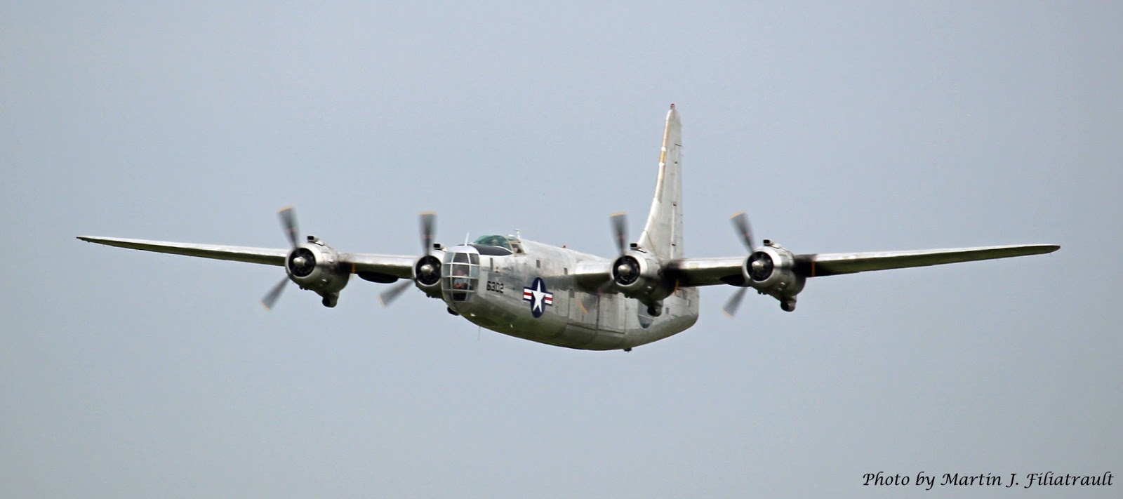
During the Thunder Over Michigan airshow I got to take some great photos in the staging area for the B-25 ride. That was the first time I was truly glad to have a flight delayed... I was out on the apron for more than an hour, and it was a great location for airshow photography. I have a photo album on my facebook page that features the best photos I took during the event, but here are some highlights:


Around mid-August I resumed my work on the RV-8, starting with cutting, shaping and deburring the rudder horn brace and stiffeners. I gave the primer a few extra days to dry and cure on the stiffeners; in the meantime I worked on prepping the rudder skeleton. Back-riveting the stiffeners to the rudder skin went pretty well, for the most part. I made up a cardboard brace to spread the skin while I riveted. Two things I should have done, but didn't: I should have made some extra carpet pads to surround the back-riveting plate, and I should have smoothed out the edges of the plate better. It left some light scuff marks on the fragile rudder skin, which will be covered by paint well enough... but for now, the skin isn't as pretty as the stabilizers I'd previously assembled.


Once the stiffeners were in place I used my bending fixture to rebend the trailing edge. This worked well and I was happy with the result.


I had to add a few more tools to the toolbox during this process. I got an electric screwdriver to save the wear and tear on my fingertips while using the deburring tool. I also ordered two more squeezer yokes from Cleaveland Tool; a flange yoke and a close-quarters yoke. These were very expensive... but they were the right tools for the job in several areas. I'm sure I'll get a lot of use out of them, so it was worth it.
After test-fitting, match-drilling and deburring the skin, it was time to prep and prime the skeleton. Once the primer had cured well, it was time to start riveting. I did a lot of research on the best way to attach the rudder horn brace. Some use blind rivets to attach it to the rudder horn. I considered it... but this required four of the specified blind rivets, and for some reason I only had three in stock. That's when I realized I'd need the flange yoke to set solid rivets there, and since that is a significant structural joint, I decided it was worth the hassle and expense to do it right. Again, I was happy with the result.


Another area of research was the best kind of RTV silicone sealant to use to tie the trailing edges of the stiffeners together. Turns out there are a lot of different kinds and brands... and a lot of different opinions from other builders. I ended up using Permatex Ultra Black maximum oil resistant sealant. It was highly recommended, and I think it did the job well. Right after applying the sealant, I got the skin riveted to the skeleton. The new yokes helped this process well, and I only had to use four blind rivets on the lower corners of the skin.


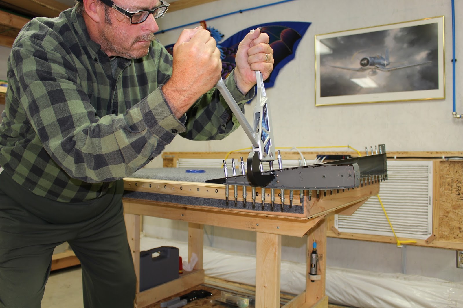


I had determined which skin edge would overlap the other to form the rudder's leading edge curve, and used the edge forming tool to put a slight crease in the overlapping skin. When the skin's edges were riveted together, the crease would help hold the outer sheet tight against the inner sheet, with no gap along the edge. The next job I faced was the dreaded rolling of the rudder leading edge. This is a daunting task, because as the rudder gets thicker from top to bottom, the profile of the required curve in the sheet changes significantly. Moreover, the curve should ideally take place closer to the spar than the edge of the sheet. This is another place that required a lot of research and thought. If you simply follow the normal rolling procedure as described, you're putting the curve in the wrong place. I learned many different ways to approach this process from numerous builders. Some say you should roll all three sections separately. Others have designed special table jigs to roll them all at once. I liked the thought of maintaining a uniform roll, so I tried the table jig method first. I cut some1/2" galvanized pipe to length and fabricated alignment blocks that would also serve as clamping points to anchor it to my table. I also used plastic sheets that would allow the part to slide easily toward the rolling jig while in use. My design of the first set of blocks didn't work out, so I had to make a second set. The first roll went pretty well, but on the second roll one of the blocks broke in half. Since I didn't want to go through the hassle of removing all the duct tape and rejigging, I carefully broke the other two blocks away from the pipe without damaging the skin and continued to roll the edge using just one clamp on one end. This worked out ok; the two rolled edges looked uniform, and the first section clecoed together nicely. But it was obvious the other two sections would need a lot more work to get the matched holes anywhere close to alignment. I cut a shorter piece of pipe and did some more curving, and then carefully massaged the pieces by hand to improve alignment, doing my best to avoid creating a crease at the spar. The closer I got, the more I realized that my initial roll was going to cause a problem, preventing the two edges from nesting together. I had to find a way to increase the roll at the root, and decrease the roll at the edge. I could visualize the process mechanically... but had trouble implementing it with the materials on hand. After trying different methods, I eventually just massaged the hell out of the parts until they were close enough to tape and then cleco into position. At this point, I was worried about two things: the shear forces that would be applied to the blind rivets by the spring tension in the aluminum sheet created by pulling the edges into alignment, and the fact that the sheet surfaces still didn't really want to nest properly. I tried calling Van's Builder Support, but coudn't get through at that particular time. So I just pondered the problems for a bit. I thought that once the two sides were riveted together, they wouldn't be moving around; the spring tension providing the shear forces probably wouldn't be a factor as long as the holes were well-matched and the rivets were tight. With clecos in every hole, I worked on the rivets one by one, starting at the center of each section and working outward. I sized each hole with a reamer because it would leave a clean round hole and keep burring to a minimum. The top section was easy, because those edges came together nicely from the first roll. The middle section was a bit trickier, but the process went well. The bottom section was a bitch. When I set the first two blind rivets in the middle of the bottom section, I could tell they popped a bit early... which was an indication that the sheets weren't nested tightly. Using a flashlight to inspect the interior of the roll seemed to confirm my suspicions. The outside edge looked fine... but the inner edge was rather wavy. That would be ok as long as I could be sure that the parts were held together tightly by the blind rivets. For the remaining holes, I used various clamping methods to make sure the sheets were nested before I pulled the rivets. When I was done, it looked pretty good from the outside; the edge forming tool had done the job well. Inside, it looked sloppy... but at least I knew the rivets were tight and nobody would see the waves along the inside edge. All's well that ends well.


Once the leading edge was finished, I installed the rudder counterweight and rod end bearings. The empennage uses seven rod end bearings for the hinges of the rudder and elevators. Six are identical, the seventh is a bit longer and is used as the bottom rudder hinge. I followed the methods used by other builders and fabricated a PVC tool for screwing the rudder hinge rod end bearings into their nutplates. Actually I fabricated two tools. I discovered that the seventh rod end bearing was also thicker than the others and I had to make a second tool to fit it. I got the bearings installed and aligned, tightened the cinch nuts... and the main rudder structure was done.


I
did some preliminary fitting of the fiberglass rudder tip. I also
continued research into lighting options, because I want to be able to fly VFR
at night. The rudder bottom that came with the empennage kit doesn't have
the faired-in tail light mounting area at the back. The plans state that
a rudder bottom with light mount is available in the accessories catalog... but I couldn't find one in the paper catalog or the online catalog. Finally I called Builder Support, and they told me the correct part number. Once I knew that, I found it online. I called Van's and asked about exchanging the parts. I elected to pay in advance for the lighted rudder bottom, using that shipping box to send the stock one back for an account credit. The new part arrived two days later, and I returned the stock part the same day.
I did a test-fit of the rudder and vertical stabilizer lying
flat on the table, and they went together well. I really wanted to mount
the vertical stabilizer upright on a table or workbench, bolt the rudder to the
stabilizer and give it a swing test. I started experimenting with ways to
do this... but as I worked, alarm bells were going off in my head.
Getting the stabilizer securely mounted upright would not be an easy
task, and if it was merely standing upright on blocks, trying to get the rudder
bolted to it, working alone, was a recipe for disaster. So I settled for
the prone test-fit. Once I have my fuselage, I'll attach the stabilizers
correctly before I fit the rudder and elevators into their working positions.
Waiting seems much wiser than risking damage to the components just to
get a cool photo.
I've already started work on the elevator
stiffeners. I should be able to finish them before winter sets in.
I knew from reading other builder's blogs that they might be tricky.
Van's even mentions in the plans that the elevators are where most
builders have trouble. So I'm going to take my time and work as carefully
as possible. You'll see the results here, of
course.