Hmmm... just what I needed... a new Blogger interface... sigh... par for the course.
It's been a disappointingly unproductive two months. Despite accomplishing one significant milestone, recently a fair number of significantly negative distractions have taken the wind out of my sails. It appears that the distractions will continue to grow in size and severity in the future, which is also disheartening. I've found some solace in photography, videography and long top-down Mustang rides... but for some reason they have adversely affected my motivation for working on the build. It doesn't help that I'm still stuck in the fiberglass phase, which I don't enjoy very much. I'm hoping that the retrospection of writing this entry will relight the fire.
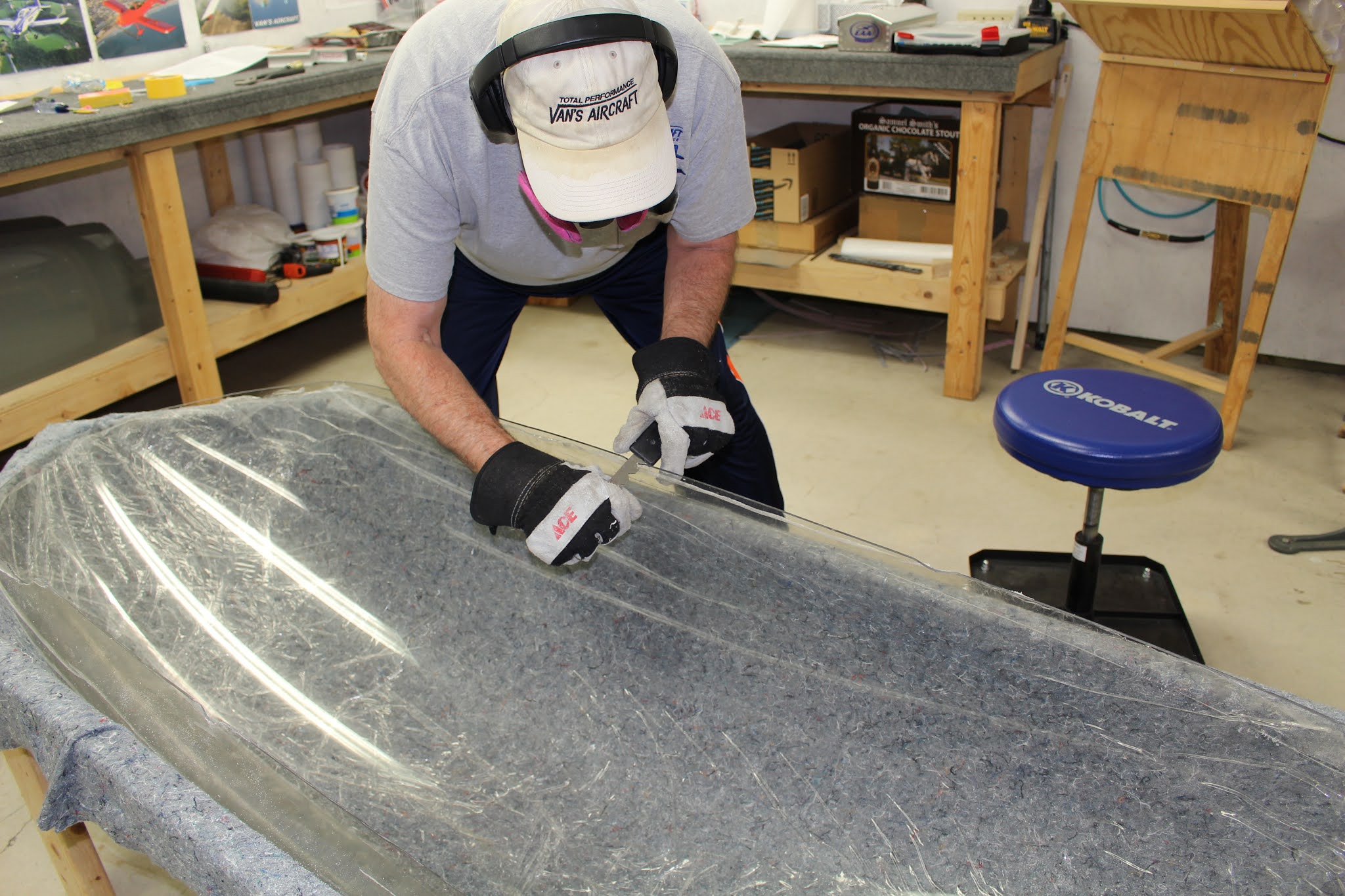
I began the canopy work by removing the protective plastic from the inside of the canopy and applying several coats of Discoat liquid polymer protectant film. This plan didn't work out nearly as well as I had hoped. Each coat was supposed to dry in ten minutes, but it didn't look like that was happening, so I waited an hour between coats. I put on four coats and let it sit overnight. When I checked it the next day I found that a fair amount of the material had pooled in the bottom of the upside-down canopy, forming a thick gooey partially-cured sludge. I put paper towel strips in the pool; as the sludge soaked in to the paper towels it aerated enough to finish curing, but the settling had left the protective film very thin on the sides. Oh well... it would have to do. The product was designed to peel off easily, leaving a clean surface. In practice I found that it adhered a little more lightly than desired and peeled off when blowing chaff out of the canopy with compressed air after trimming. I ended up removing the coating and applying delicate surface masking tape to strategic areas, along with strips of the light-adhesive floor masking plastic. I experimented with different ways of masking off the cockpit and fuselage during canopy work; some of these methods proved unworkable. I also cut the recommended cardboard buffer plate that fits between the windscreen support and canopy frame hoops. I actually cut two; the first one was double layer cardboard and turned out to be thick enough to displace the canopy frame slightly, so I had to cut another out of single layer cardboard.


When doing initial canopy fitting, I realized how beneficial it would be to have experienced helpers, so I contacted test pilot and RV-8 builder Terry Lutz and asked if he would be available to help. We scheduled a date to do the trimming and the Big Cut. In the meantime I took care of some other tasks, having my data plate laser etched by Quality Business Engraving and making a jig to protect the end corners of the flap hinges while the wings were stored in the cradle.


Terry Lutz and Carl Franz showed up on the designated Saturday and we got to work. They assessed the situation and we moved forward with the trimming. They guided me through the process and suggested the best techniques for trimming and smoothing the edges. Carl provided an excellent plexiglass edge smoothing tool that helped a lot. The canopy frame hoop tube ends needed to be trimmed down a bit to better fit the canopy profile, allowing the canopy to nest on both hoops better. We didn't quite get to the Big Cut, but they got me going in the right direction.


I worked for a few days doing more trimming and other miscellaneous tasks. I worked on determining locations in the cockpit for the fire extinguisher, canopy snapping tool and document pouch. Rich Hwang helped me with handling the canopy during one trimming session.


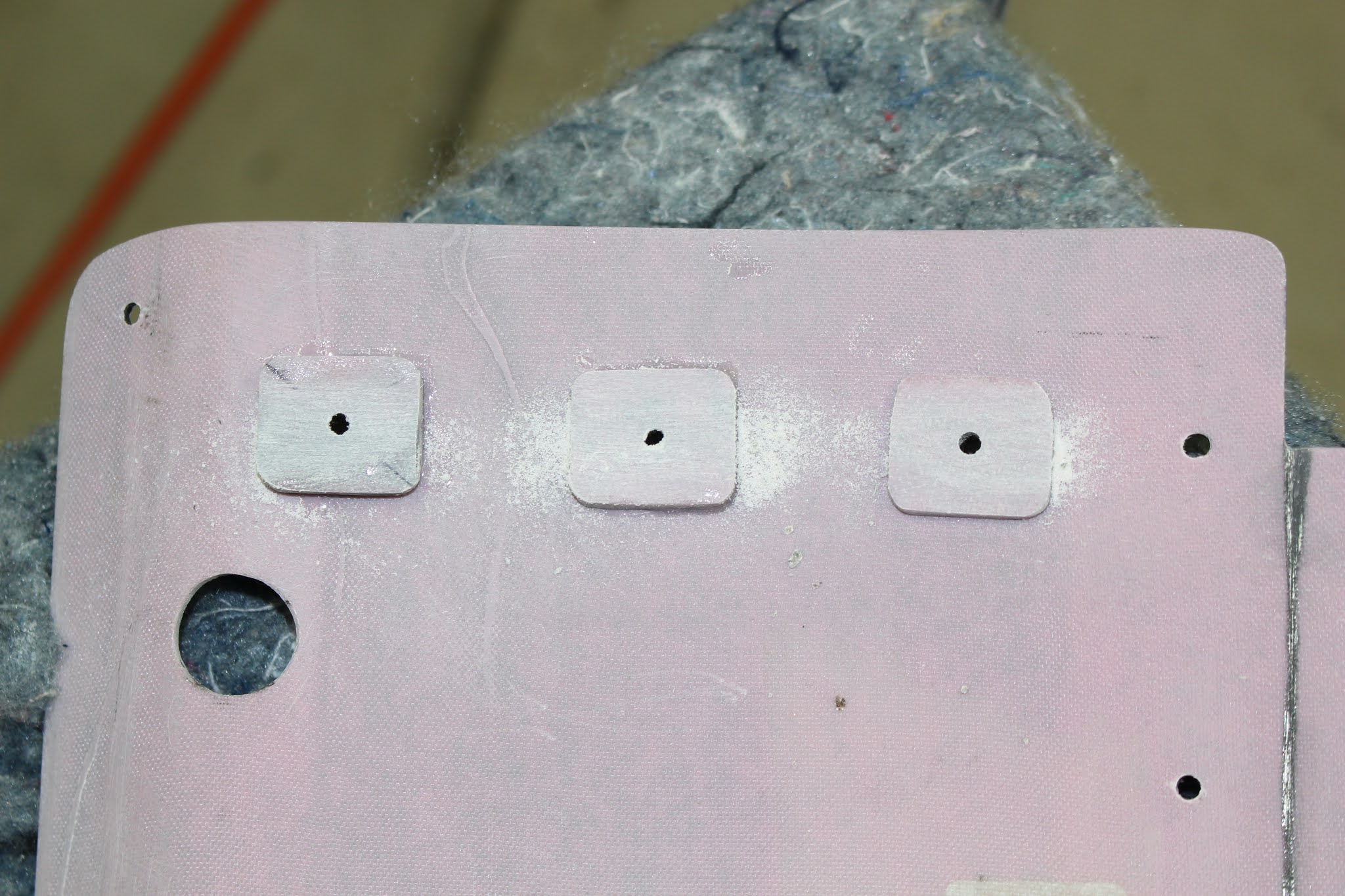
I decided to put the fire extinguisher on the back of the front seatback. The extinguisher bracket was taped in a couple locations; I sat in the seat and made sure I could reach the extinguisher, release it and bring it forward with either hand. The optimal location was determined and 1/4" bolt holes were drilled through the seatback. I had hoped to place the bolts through the seatback and into the extinguisher bracket, but the tight fit of the extinguisher against the bracket required that the bolts be inserted from the bracket side. The screws protruded through the Velcro seat retention strips; the plastic seat back had to be notched with holes to allow clearance around the bolts, nuts and washers. Velcro was also applied to the left cockpit side panel for the plexiglass breaker tool.


When the installation was complete, I performed and videotaped some deployment tests. I shared this with the Van's building community and received a lot of valuable feedback. Based on suggestions from experienced pilots and builders, I will also be installing a smaller extinguisher in the front, on the right side console cover. See link below for video.


Trimming continued, and I continued to seek additional advice from Van's and other builders. As the fitting got closer, notches were required to clear around the vertical skirt support tubes on the canopy frame. Sanding, smoothing, fitting, checking, removing, sanding smoothing, fitting... the litany continued until I was ready for the Big Cut. The canopy was clamped and taped in place; the cut line was established and laid out, flanked by fine line tape and masking tape. The cut was done carefully and successfully. I now had a separate windscreen and aft canopy. They were then removed and the cut edges sanded and smoothed; the masking was removed and the cockpit and fuselage were cleaned up.


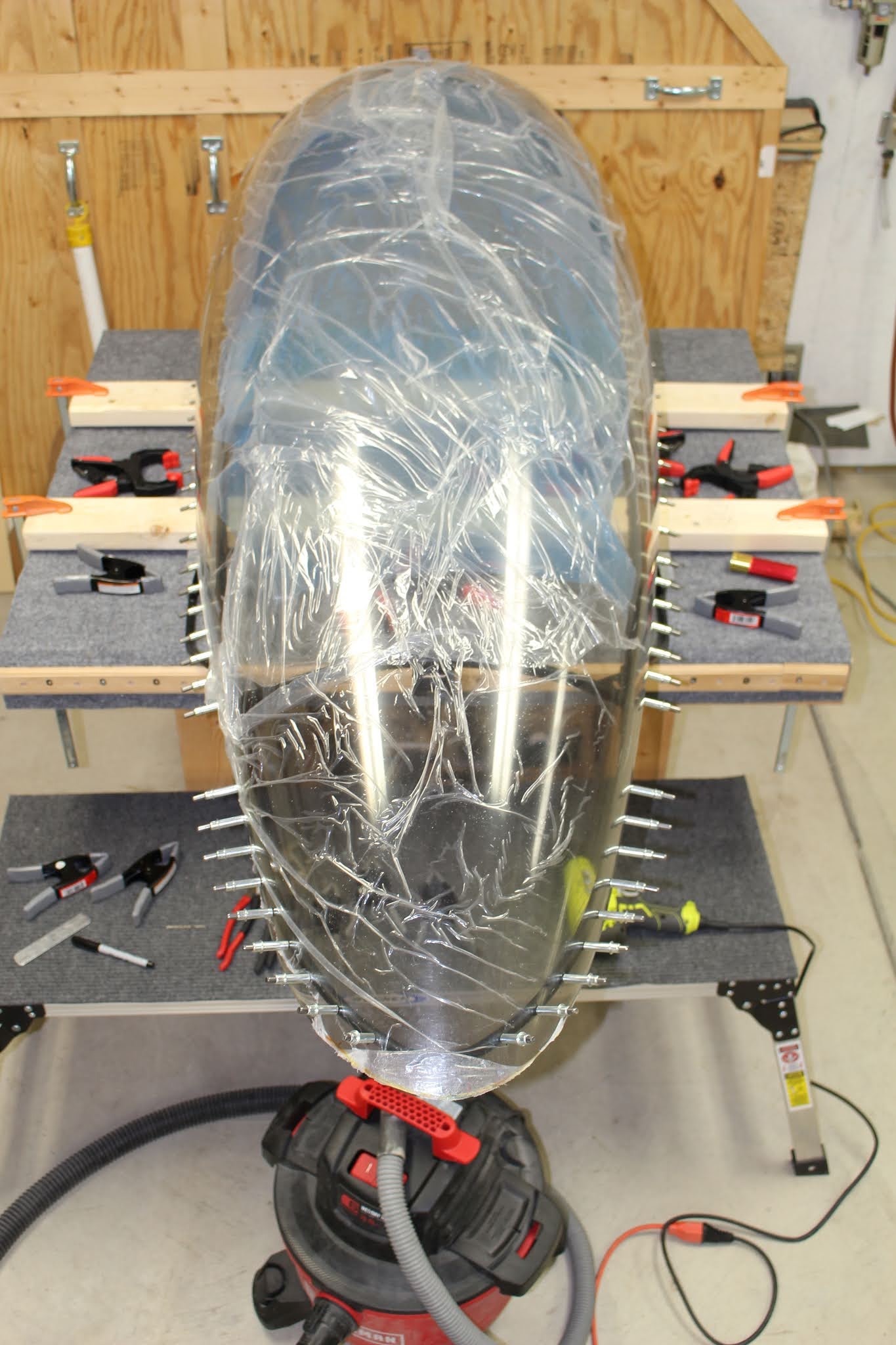
The canopy frame was removed and secured to the C-frame table. The windscreen was remasked on the inside and temporarily taped to the windscreen support and forward top skin. As the canopy trimming and fitting continued, I was alarmed by how poorly the canopy seemed to fit the frame; There were wide gaps at the aft sides; the canopy could be clamped into shape along the frame but I was worried about building stress into the assembly. I conferred with Van's and other builders and it was suggested that the canopy should be clamped from the aft end forward. Fellow PTK tenant and experienced composite builder Curt Martin came out and looked at the fit. He told me that if the plexiglass could be held in the correct shape easily with spring clamps as demonstrated, it should be fine once assembled permanently. Later on, I noticed that Van's had acknowledged the loose fit gaps in the instructions. I fabricated a pilot hole drill guide template out of scrap aluminum that could also be used to mark a 5/8" edge distance from the rivet holes. The notches for the vertical tubes were enlarged as the clamping process was refined. With the canopy clamped to the frame in the position intended for riveting, the holes were marked on the plexiglass using the spacer and spinning a long bit by hand to mark the location. A hole was drilled through the plexiglass with a dull #40 bit, which also started the hole on the steel canopy frame below. Swapping to a sharp bit, the hole was extended into the horizontal canopy frame tube and a cleco inserted. Spacing had to be adjusted to account for distance between vertical skirt supports and the spacing specified in the plans in the aft area where the tubing diameter was stepped down. Eventually, the horizontal row was complete all the way around and the canopy clecoed in place.


I made a new canopy hole guide template for the forward canopy bow holes; the previous template holes were oversized from the previous work and the new template had a 9/16 edge spacing per plans specs. The same process was used to drill the holes in the forward canopy bow. All pilot holes were now complete.


The canopy was removed and the holes in the canopy frame were final drilled to #30 and deburred. The pilot holes in the canopy were final drilled with a 5/32" plexiglass bit and deburred inside and out with an abrasive fiberglass countersink bit. Guide tape was laid out for the final trim cut of the bottom edge. The aft tip was rounded and reshaped; the cut edge was sanded, scraped, smoothed and polished. One of the layout guides was modified for use as an edge marker for the final cut of the forward edge. The edge was marked, guide tape laid out and the final cut was made, sanded, scraped, smoothed and polished. All edges were inspected and any remaining flaws polished out. All holes received a final polish inside and out with 400 grit sandpaper and the finished canopy was clecoed to the frame with #30 clecos.


Neighbor James Turner helped me put the canopy and frame back onto the fuselage and the fit was checked. The top aft corners of the forward top skin and the left corner of the canopy were trimmed to allow better canopy clearance. The windscreen was retrimmed along the aft edge; sanded, scraped, smoothed and polished. The forward edge of the canopy was also resanded, smoothed and polished to improve the fit.


The canopy frame still sat a bit too high in relation to the windscreen support and measuring each side against the fuselage indicated an imbalance. The trim amount for each side was calculated and tube bottoms were cut... but unfortunately the trim measurements were not transposed correctly when the canopy frame was inverted for cutting. As a result, each tube end was cut to the wrong length. One tube would need to be retrimmed, then both tubes would need shim washers. Washers were dressed to fit the canopy rollers and painted black. With the canopy frame height finalized, the mounting screw holes were drilled through the canopy frame tube ends and the roller tubes.


With the canopy roller mounting screw holes drilled, the sliding canopy latch could be assembled. This is a latch mechanism that allows the canopy to be held halfway open using a pivoting cam arm. When the canopy is opened, the arm slides over the catch block mounted to the fuselage. When the canopy is pulled a bit forward, the cam arm slides over the catch and rests on the block. Then the canopy can be slid back again and the cam arm fits into the catch and holds the canopy in place. To release, simply pull the canopy forward enough to allow the cam arm to drop off the block; when it slides backward there it will once again ride over the block and catch and the canopy will open completely. It's an ingeniously simple design by Mike Zeller and sold by Flyboy Accessories. Matt Dralle shared a video of how it works on one of his YouTube channels. Here's a link:
A test fit of the latch components indicated that I'd need to fabricate a spacer for the latch block to align it with the travel of the cam arm. The half-round bolt spacer needed to be trimmed to fit my canopy frame and roller placement; the stock roller mounting screw was replaced with a longer bolt supplied with the latch kit. The aluminum parts were painted and bolted to the fuselage. When the can arm and spacer parts were bolted to the canopy frame, it became evident that I hadn't drilled the bolt hole as perpendicular to the slider as I had hoped; the assembly was slightly clocked forward, but it still worked. I torqued the nuts to spec and marked them with torque seal. In retrospect I realized I shouldn't have bothered; the canopy will have to come off and on several more times before final assembly.


With the canopy fabrication essentially complete, work could begin on the skirts. It didn't begin well. The first step was to make up the transfer templates drawn on the plans for the rivet holes in the vertical tubes from spare aluminum sheet. Once drilled in the tubes, these holes couldn't be match drilled with a strap duplicator; hence the templates. Initially I planned to make two templates; one for the middle vertical tubes and one for the aft vertical tubes. They could be flipped; one side for the left tubes and one side for the right, which would compensate for any differences in intersection angles between the vertical and bottom tubes from side to side. I marked the hole locations with the completed templates on the right side and drilled the #40 pilot holes in the tubes. When I was done, I realized that on one hole the drill bit had walked a ways off the mark before penetrating the tube. Now it wouldn't align with the template. No big deal; I'll just enlarge the hole in the template to compensate. I enlarged the hole with a jewelers file, bending the file in the process... then realized I had enlarged the correct hole, but in the wrong template. Great. It was obviously going to be one of those days that I really shouldn't be working on the airplane. Took a deep breath... and took a break.


The next day I modified the other template and got one set of pilot holes drilled, using a strap duplicator to match drill the bottom corner holes in the template. Still wasn't happy with the alignment and came to two conclusions. Flipping the templates for right/left sides wasn't a good idea; I wanted four dedicated templates. I should also drill the holes in the frame tubes first, drill one pilot hole in the center of the template, then use a strap duplicator to match drill the rest of the holes in the template. So the templates were made and the holes were drilled with much better accuracy. When those matched pilot holes were completed, the remaining holes in the lower skirt tubes were measured, marked and drilled.


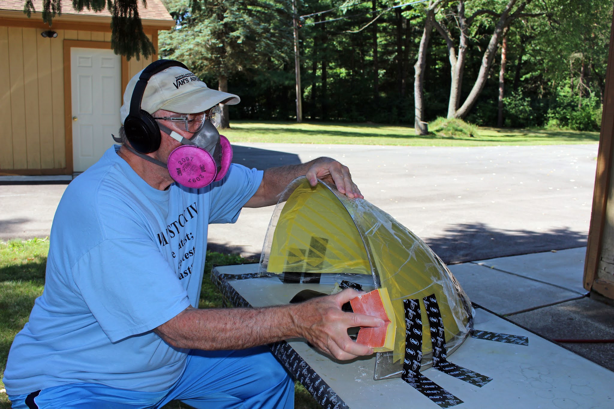
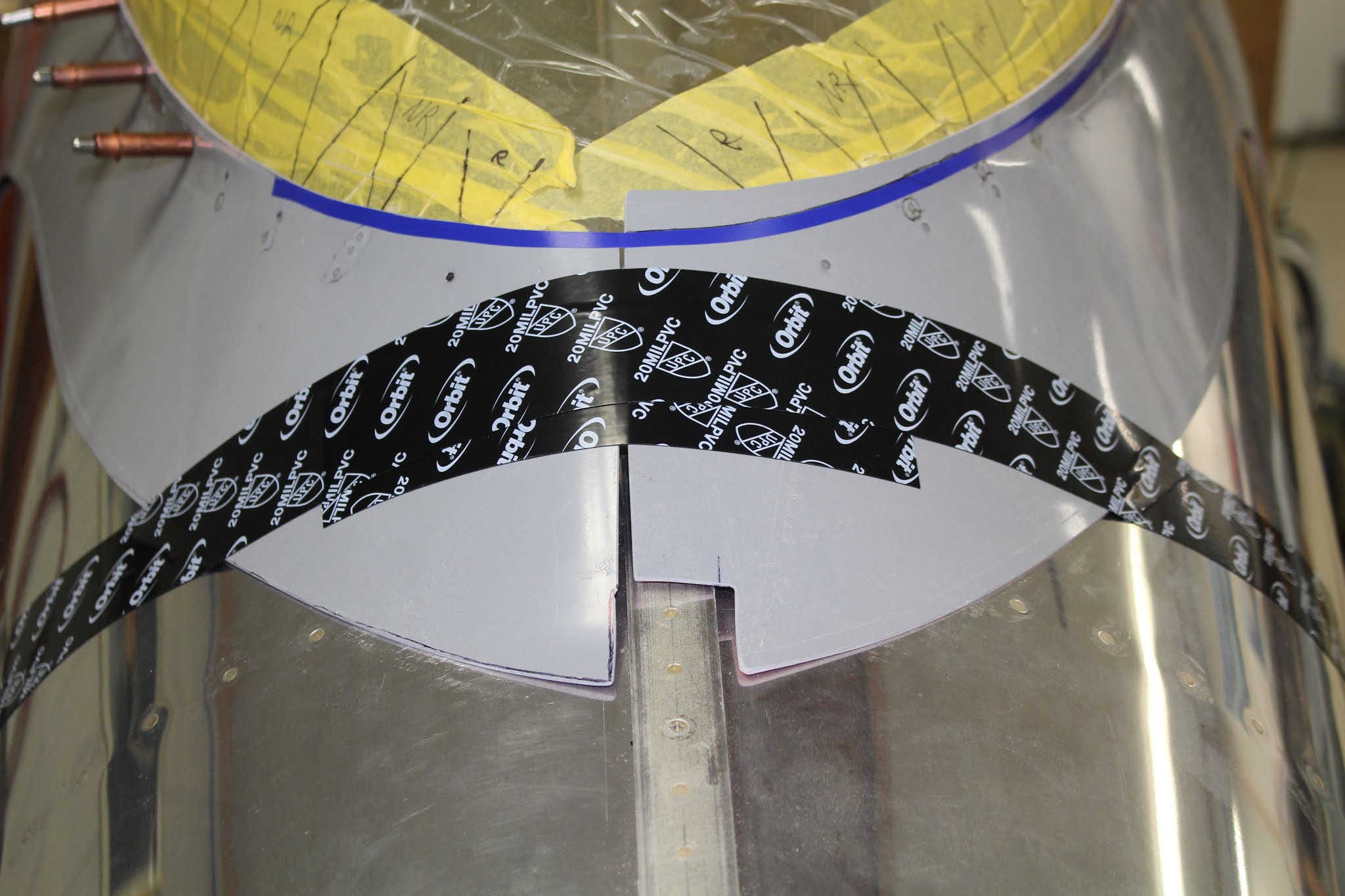
The frame was ready for the skirts; now to get the skirts ready for the frame. The plans called for a first trim of each skirt 1/4" outside the guide lines molded into the skirts. I used 1/4" fine line tape to set a cut line around the perimeter of each skirt. Each skirt in turn was secured to a card table with packing blankets and a strap. As with the plexiglass, trimming and sanding fiberglass is messy work that is best done outside if possible. When that was done, the canopy was temporarily riveted to the frame along the bottom canopy tube in strategic locations. Masking tape was applied around the bottom edge and intersecting lines drawn to show the rivet hole locations; temporary rivet locations were labeled.


The first time the skirts were positioned on the frame was reminiscent of the initial fitting of the canopy: how on earth is this really going to fit? One problem had been staring me in the face for months: I should NOT have riveted the bottom aft corners of the top forward skin to the fuselage. That rivet hole in the fuselage should have been riveted prior to fitting the top forward skin and there really shouldn't have been a matching hole in the top forward skin at all. The aft bottom corner of the skin should have been left loose to allow the forward edge of the skirt to slip underneath it. But there was no mention of this possibility in the instructions and the plans did not indicate it should be left open, so I riveted it. This is one of those places where the final solution to assembly is determined by the builder, and everybody does it a little differently. Some builders trim those aft sections of the the top forward off entirely and have the skirt butt up against the skin when the canopy is closed. Others have the skirt tuck under the skin as well as the fiberglass lip that is glassed in over the windscreen which overlaps the forward edge of the canopy. I really didn't want to have to trim the assembled and painted skin or drill out that corner rivet, because that would leave an open rivet hole through the fuselage skin and longeron. I could enlarge the open rivet hole in the top forward skin and set a blind rivet in the fuselage. But what I really want to do is keep the integrity of the existing assembly intact and find a way to work around it with the fiberglass. So the first thing I did to fit the skirts was to cut notches on the forward bottom corners of the skirts so that they would slip underneath the aft edges of the top forward skin. Then the #30 holes along the bottom of the canopy were match-drilled along the top edge of the skirts. On this initial fitment I did two things wrong: I didn't tape the skirts in place with the canopy closed to determine the best fit of the skirts along the tricky intersection of the canopy and lower canopy frame tubes, and I didn't fit the skirts from the aft end forward, as suggested in the plans. These tips could have saved me a lot of grief later. I've said it before, and I'll say it again: read the plans and instructions thoroughly, frequently and repeatedly. Another tricky area of the skirt fabrication is match drilling the rivet holes on the diagonal section of lower skirt tubing that angles up to the canopy bottom tube. The plans suggested fabricating an oversize strap duplicator with scrap aluminum and a partially set rivet. But I thought I'd try making an aluminum template, as I had for the vertical tubes. This would be a long piece whose orientation would be set by the position of the forward rivets; from there the remaining hole positions in the template could be set with a strap duplicator. I made one template for the right side, and got most of the #40 pilot holes match drilled in the skirt. But my new template let me down. The offset caused by the thickness of the skirt, compounded by a gap between the skirt and the frame tube, caused the last two holes to be mis-drilled, putting a nice gouge in the powdercoating. Sigh. Oh well. Fiberglass can be patched. I'll figure out a solution later.


Switching to the left side, I match-drilled the #30 holes in the top edge of the skirt, making the same errors I had made on the right side and adding one more. In addition to not taping the skirt down and working from the aft forward, I really should have drilled the large hole for the canopy latch tube and fit the skirt properly into the notch between the canopy bottom edge and lower frame tubes before match drilling the holes. Another situation I began to realize with experience was that the thickness of the strap duplicator pad could cause a slight offset to the hole location; some match-drilled holes didn't align very well after the duplicator was removed; they would have to be patched and re-drilled. For the aft diagonal tube holes, I made the homebuilt strap duplicator shown in the plans; as it turned out it wouldn't work well enough to use. As I worked aftward with each skirt, it became evident that the fit was deteriorating badly. I considered chucking the parts, buying new skirts and starting over. But fiberglass can be fixed and altered; many builders have had to create their own Frankenskirts. Looks like I'd be one of them... but how? I'd just have to figure it out. Fitting, trimming, adjusting and refitting continued; holes were drilled and abandoned. On the front ends it became obvious that I would have to trim some of the top forward skin aft edges, but I'd work that out later. I tried using the spherical magnet trick to set the locations for match drilling the diagonal tube holes; it was not as effective as I hoped. Eventually I resorted to reaming some skirt holes oblong to assure proper cleco fit, marking where I'd have to patch them later. It felt like stumbling in the dark... but it was progress.


The aft skirt ends were trimmed and the notch cut for the canopy rail. Skirts were removed; bad holes filled; refitted and re-drilled. In order to match drill the holes in the skirt where the temporary blind rivets were set, I set new temporary rivets and drilled out the old ones. One rivet spun in the hole and was difficult to deal with, but it was removed. I took a rivet count and learned that Van's had supplied enough rivets for the assembly but hadn't taken temporary rivets into account, so more were ordered. To locate and match drill the last three holes in skirt along the left aft diagonal tube, I inserted long rivets into the pilot holes, put a dab of torque seal paint on the head of each rivet and carefully clecoed the skirt into position. The skirt was removed and #40 pilot holes were carefully drilled from the inside out on the paint marks. Not as accurate as I had hoped, but adequate enough to get the pilot holes drilled. Now most of the holes were drilled, except for patched holes over new temp rivets. I put the skirts on, closed the canopy and checked the fit again. It looked terrible. This was getting really frustrating.


To get my mind off the terrible fit, I decided to work on another custom detail I had in mind. Many builders mount a handle or knob on the aft end of the canopy to make it easier to pull open, especially if the fit is tight. I originally purchased a stainless steel drawer handle for this purpose. When I thought how it would be mounted and the stresses that would occur during use, I determined that a knob would be better and easier to install with a screw that would pass through the canopy frame, canopy and skirt. I found a somewhat streamlined lozenge-shaped stainless steel knob at my local Ace hardware store that would work; I may even shape it into a more streamlined teardrop before final installation. I laid out the location for it, drilled a pilot hole through the canopy and frame and enlarged the hole to accommodate the screw. Checking the fit showed the hole to be the proper angle but slightly forward of center. The head of the screw wouldn't be evenly supported by the sloping surface of the bottom of the frame tube; a small bit of reinforcement steel should be welded onto the tube to strengthen the assembly enough to endure the stress of frequent use. Sigh... another small but important job that I'm not equipped to handle (I'm not a welder) that will damage the powdercoat on what was supposed to be a finished part. Throwing that task onto the pile of future problems to be solved, I moved on.


Must get back to work on the skirt. The lower skirt rivet holes were enlarged to #30 and fiberglass shims were fabricated to take up spaces between the tubes and the skirts in several places. I laid out and trimmed new top edge lines on the skirts. Lots of trimming, sanding, refitting, checking, removing, sanding, refitting, checking and repeating. Still not happy with fit. Even tried heating the aft ends of the skirts to get them to relax and conform to the required shape in back, with little success. Patch holes; drill holes; ream holes; check holes.


Some much needed distraction was provided during this period by tackling unrelated tasks. While showing the build to some interested relatives, I pulled the top cowl off and it reminded me that the dehydrator plugs would need some fresh desiccant. I also experimented with mounting positions for my Garmin Virb camera inside the cockpit and making a test video. It revealed that I would need to find a longer mount extension to get the camera where it could see the panel and out the front windscreen and not be blocked by my shoulder or head. The extension was purchased online; delivery was delayed due to the current COVID/USPS administration debacle. Another test video showed that the new extension will be useful, but for the best coverage of the cockpit I will probably be better off using a body or harness mount.


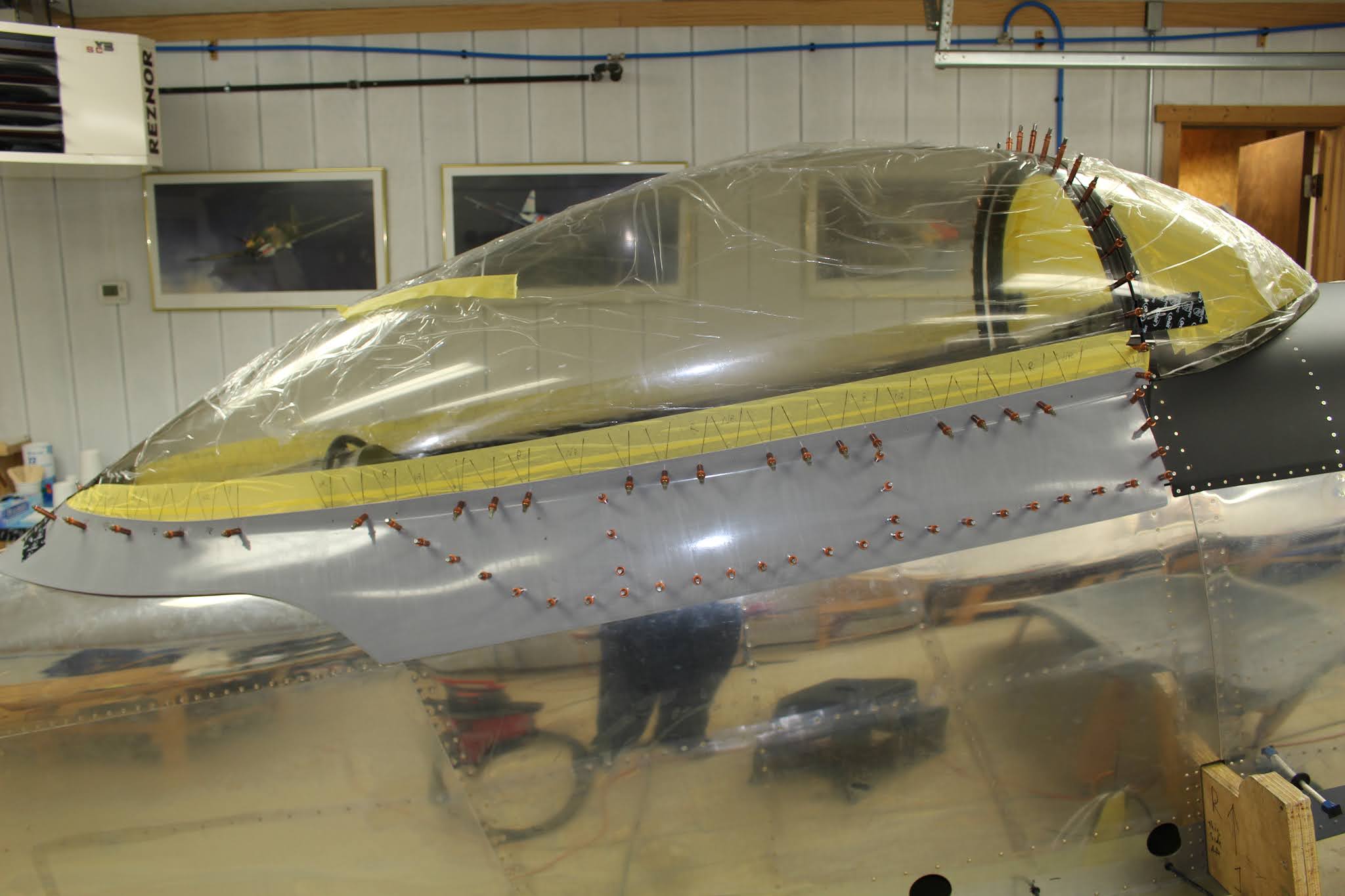
More skirt trimming and fitting. I tried a variation of the torque seal marking trick again, putting a drop on the center of the new temporary rivets where matching holes would need to be re-drilled. The holes were drilled with an undersized bit and locations were checked against the temporary rivets before being adjusted and drilled out to #30. With all holes now drilled where needed, they were machine countersunk for the flush blind rivets with the abrasive fiberglass countersink bit. The masking was altered around the bottom of the canopy and protective plastic was pulled back from areas covered by the skirts. Vinyl tape was laid down around the bottom edge to protect the plexiglass during the riveting, bonding and filling of final assembly and finishing.


This is the current state of affairs. The progress was fractured and slowed by all the other tumultuous events that have been swirling through my life for the past two months... some good; lots bad. We'll make it through, and I'll get back on track with the build. My scheduled training with Bruce Bohannon in September was postponed. It's looking very unlikely that this aircraft will be ready to fly before next winter, and Bruce strongly recommends that training should happen right before I fly my own airplane, so I'll have to reschedule probably next spring. At least I've managed to stay current in Crosswinds' DA40s and even gotten some tailwheel recurrency in the Ann Arbor Aviation Center Citabria. Unfortunately due to the border closure I have no idea when (or even if) I'll be able to revisit the Canadian Historical Aircraft Association for more Chipmunk flying and volunteer work. It also remains to be seen whether I'll get the intended painting done on the plane this year. If I know the fuselage will not be flying this year, it should be kept in the heated shop during the winter to keep the engine as well preserved as possible. I may finish the canopy and windscreen to the pre-paint stage, or I may swap the wings over to the shop and work on finishing them before getting the fuselage back over to the heated shop and finish the canopy and windscreen during the winter, then paint everything in the spring before final assembly at the airport. I'm going call audibles for a while and make sure progress is made. Whatever happens, you'll know. Stay tuned.