A lot got done in the past two months, starting with a lot of little steps. I bought and installed desiccant plugs in the top plug holes of each cylinder of the new engine. Continued with wiring the fuselage: battery cables; wire extensions; connectors; routing; heat shrinking; etc.


I worked on the elevator trim some more and got it configured as much as possible prior to final assembly. Once I worked out how to route the cable through the horizontal stabilizer and how it attaches to the elevator and trim tab, I had to reroute the cable at the front to get enough slack at the back end. This meant drilling another hole in the gear tower to tighten up the loop to the vernier. Once it was done and I did a temporary assembly with clecos to the elevator trim cover, I adjusted it for proper travel, and it worked well. It's an odd design; the final adjustments have to be made before riveting the adjustment nut to the cover, then the cover is screwed onto the bottom of the elevator as part of the final assembly. This essentially tethers the horizontal stabilizer and left elevator to the aircraft; any subsequent removal of either would require drilling out the rivets to to remove the nut plate from the cover, unscrewing the nut plate from the cable, and removing the cable from the elevator and horizontal stabilizer. Oh well. At least I know it will work when I do assemble it for the last time.


I assembled the tailwheel for the first time and discovered a significant misalignment in the tailwheel fork weldment. When assembled, the steering arm fits over the fork axle shaft and a spring-loaded key slide. If the fork is in trail position, the steering arm and wheel axle bolt should be parallel. When my fork was welded up it wasn't aligned correctly in relation to the key slot, so the steering arm and wheel axle bolt were a few degrees out of alignment. The tailwheel itself also had issues; the bearings were not fully pressed in place and were also out of alignment. The combination of problems left me with a tailwheel assembly that I considered unacceptable.


I sent an email documenting this situation to Van's Builder Support and they agreed with my assessment. They instructed the parts department to send me a new fork weldment and tailwheel free of charge, and told me not to bother sending back the rejects. The replacements came together much better than the old parts, and with shim washers in the right place on the wheel axle bolt to provide the correct clearances, I'm very pleased with the result. Once again, Van's stood behind their product, making sure it was the way it should have been. Eventually I had the forks powdercoated flat black.


Some other small steps included working on the firewall, drilling out the engine mount pilot holes to fit the 3/8" bolts and enlarging the engine control cable holes to 1/2" to accept the required snap bushings. I got the cables assembled to the throttle quadrant and adjusted properly. When I attempted to assemble the quadrant back onto the fuselage, I discovered another strange anomaly. I had fabricated the cable stay angle bracket per the dimensions in the plans; the three mounting holes are arranged in a triangular pattern. The quickbuild fuselage has the cable pass-through holes drilled in the front and back of the left gear tower in a triangular pattern... but the spacing between the holes in the gear tower doesn't match the spacing on the cable stay bracket, so when I passed the cables through the gear towers and attempted to get the quadrant into place, the cables bound up on the inner edges of the aft gear tower holes. I had to remove the cables and ream out the inner edges of the cable holes so that I could get the cables to pass through the tower without binding up as I pushed the quadrant forward and into place. I also cut custom rubber grommets to fit around the forward gear tower cable holes. It was a lot harder to get those installed than I expected because access was difficult. Weird; fiddly; but another job done.


I also removed the windscreen support weldment and had it stripped and powdercoated flat black. I masked the cockpit and panel and spray painted the forward cockpit rails flat black. Then I bolted down the windscreen support weldment, torquing the stop nuts to spec and marking them with sealing paint. I gave a lot of thought about whether or not I would need to pass any more wires through the bulkheads above the spar pocket. Once I was certain it was safe to do so, I riveted the left bulkhead cap in place. That allowed me to do a final installation of the throttle quadrant and aileron trim panel. It was pretty cool to see the cockpit starting to come together.


Going back to firewall work, I fabricated the support angle for the sender mount and drilled the holes for mounting the starter relay. Some initial confusion about hardware call outs on the plans and actual inventory led to another call to Van's Builder Support and some hardware ordered from Aircraft Spruce.


I also started work on the cockpit heat selector box and quickly realized I would have to customize my installation. The cable routing described on the plans would not work for my aircraft because of my engine wiring harness installation and potential fouling of the rudder pedals. I decided to reroute the cable, modify the flapper lever and change the direction of the cable actuation. I checked the angle of travel on a cardboard template, designed a cable anchor bracket to facilitate the redesigned actuation travel and bench tested the new design before installing. The cable would be installed through the left gear tower; another difficult installation working inside the cluttered and cramped access of the gear tower. I cleaned and degreased the firewall and heat selector box, applied RTV sealant to the mating surfaces and bolted the box in place. The actuator cable had to be cut to length and the cable wire bent to fit into the hole in the flapper lever. The finished assembly works opposite of the stock setup; now it is intuitively similar to a mixture control: push for on; pull for off. After examining and testing the assembly I realized that the actuation was good, but the incoming hot air was directed toward the front side of the gear tower... and toward the fuel pump, fuel lines, brake lines and wiring. I decided to fabricate a diverter cuff to redirect the incoming hot air straight back toward the center of the cockpit. The modified actuation would make this tricky; a slot for the cable would be required, but the new actuation bracket would also serve as a mounting bracket for the cuff. More test fitting; fabrication of mounting tabs; prepping, priming, drilling and riveting resulted in a fairly effective installation.


Another custom part I designed was a battery tray adapter. I chose to use an Odyssey PC-680 battery for the airplane, which is considerably smaller than the usual car or aircraft battery that Van's designed their aft battery tray to accomodate. I thought about building up an adapter tray out of wood, but what I had in mind lent itself well to 3-D printing. I came up with some specs and crude drawings and sent them to a friend and fellow EAA Chapter 113 member, Oliver Reik. He made up some CAD drawings and printed me an adapter that was just right. That battery is popular with the Van's RV community, so there's a market for this part and some 3-D fabricators are rising to meet the demand. I'm hoping Oliver can get a piece of the action.


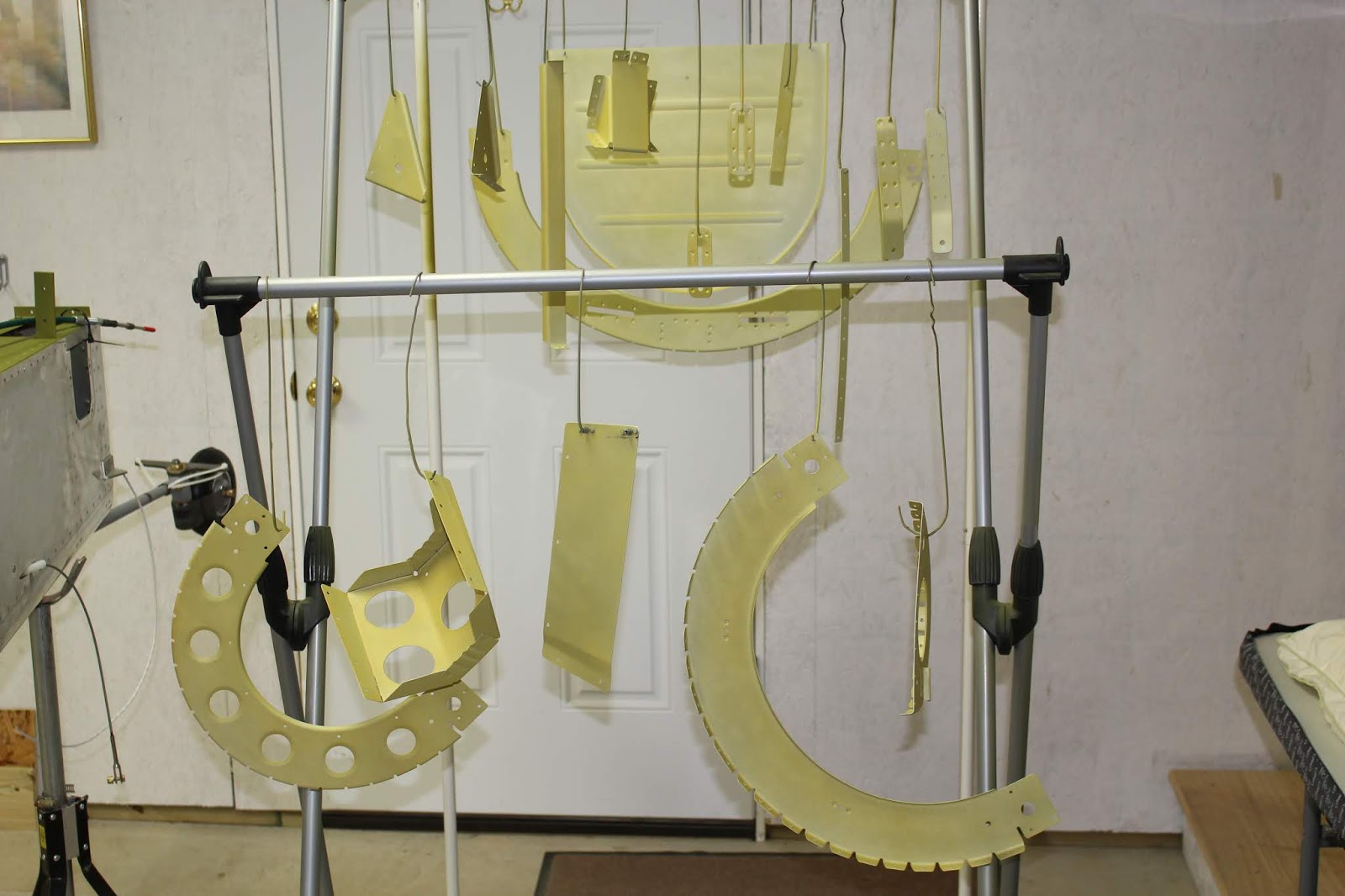
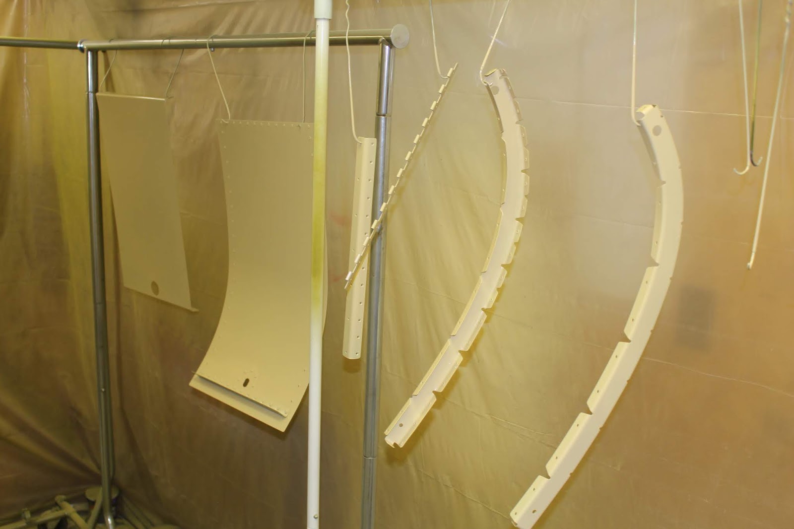
Spring was late coming to Michigan and it took forever for the weather to get warm enough to paint the batch of parts patiently waiting for prepping, priming and painting. So more small steps were required to keep the project moving forward. I continued on wiring tasks and routing; got the main wheels assembled; determined antenna locations; fabricated a top spacer for the battery hold-down bracket out of an old polypropylene cutting board; drilled locating holes and designed and assembled a bracket for the GMU-11 magnetometer.


Finally it got just barely warm enough to paint in the woodshop paint booth, so I got to work prepping and wash priming the aft bulkhead tops. I riveted the harness fairleads, nut plates and mounting tabs to bulkheads before applying the top coat of interior green. I skipped the primer because most of the other interior painting was applied directly to the Van's wash primer, and once assembled these parts would receive very little wear and tear. Just before I shot the top coat, I realized that the paint had exceeded its expiration date by a few months. I called Ryan at Blend Supply; he checked with his contacts at Sherwin-Williams and they said that if the material was very thoroughly stirred and filtered prior to application, it should be fine. The top coats took much longer to dry than usual, and that had me worried at first. But the parts did eventually dry thoroughly, much to my relief. I think the lower temps had a lot to do with the long cure time.


In the midst of many different little steps, there came a big step. After four months of delays, I finally got word from Whirl Wind Aviation that my 200RV propeller, governor and spinner would be ready for pickup in mid-April, so I made my travel plans to drive to Austinburg OH on Sunday April 15 and meet up with an old high school friend that evening to drink beer and share stories. I would visit the Whirl Wind Aviation location on Monday morning, pick up the prop and drive home that afternoon.
The beginning of the trip was struggling through more terrible weather. It got me thinking... my quickbuild kits were delivered in freezing rain; I drove through freezing rain to get my engine... and I had to drive through freezing rain to pick up my prop. Not sure if the gods are trying to discourage this build... or wishing me cool running!
Whirl Wind shares a large facility with Titan Aircraft Supply and Future Controls Corporation, and when I arrived Nichole gave me a tour of the facility. Some very cool things are going on in that building. When I got home, I decided to leave the prop and spinner boxes unopened until I had the engine mounted.


Back to the little steps, I continued working on wiring. Paying the premium for having Aerotronics build my panel was worth every penny; I'm all about the "plug and play" concept. But there are some peripherals that have to be figured out. My brain's first response to these issues is to pop like a tiny fuse. I find mechanical concepts more intuitive to comprehend, and I do grasp the basics of electricity. But when faced with the seeming complexities of interfacing electrical and electronic components, my brain tends to revolt. (Get it? Re-Volt? Yeah... ok... sorry). Reading a wiring diagram is one thing; I can figure out the symbology and signal paths, but when it comes to actually physically running the wires, I need to see actual installation photos. It doesn't help when I double-check my understanding of required connections by checking multiple sources and I find discrepancies between the sources; particularly the Van's wiring diagrams and illustrations. Connecting the master relay to the starter relay is a good example. Research taught me that the master relay should be as close to the battery as possible and the path of subsequent connections. In most of the Van's diagrams and drawings, they indicate the right way to interconnect the two relays... but one illustration of the cable running from the master relay to the starter relay seems to show it connecting to the opposite pole of the starter relay than all the other sources indicate. Another illustration contradicts the master relay connection. Are these wrong... or just sloppy drawings?


I know that I'm dealing with DC power here, so direction of current flow can be an issue. Does it matter in which direction the current flows through the starter relay? After all, that relay is nothing but a switch, so it really shouldn't matter. But with my limited grasp of electronic concepts, I'm always uncertain that I'm missing some unknown but very important aspect of the connection. We all know that in many instances if you connect it wrong, it blows up. With modern glass panel avionics, if you hook up your battery wrong, you'll fry every single component in the chain. That's a very, very expensive mistake. Knowing that tends to make me very cautious, even in the most minor connection decisions. I will agonize over any uncertainties, and progress slows to a crawl... but I know that it is far better to lose some time getting details right than hurrying a process and botching it, causing a huge loss of time and costing thousands of dollars. So I called Jason at Aerotronics and sent emails to Van's Builder Support seeking clarification, and arrived at a consensus. It would seem that the drawing inconsistencies I spotted were indeed errors... so I think I have it right now. Lots of time was spent on very little progress, but little steps will always be better than big stumbles.
With the paint on the bulkhead tops finally cured, I could move on to a much more enjoyable job: riveting the aft bulkhead tops to the fuselage. Using the squeezer, I started by riveting the tie down ring receptacle nut plates to the bulkhead gussets and the canopy rail receptacle to the forward bulkhead top. All bulkhead tops were clecoed to the fuselage bulkheads and starting with the aft bulkhead top, I riveted each one in place and riveted the bulkhead gusset assemblies to the fuselage and forward bulkhead. Then I bolted the GMU-11 and ELT brackets into place.
This all went well, but I did build in one tiny flaw. Because of the way each bulkhead is positioned most are riveted with the skin flange forward and the round manufactured head of the rivets facing aft. However the large forward bulkhead has to have the skin flange facing aft and the manufactured heads should all face forward, especially because they will be visible from the cockpit. This all occurred to me right after I set the very first large bulkhead rivet. I thought about drilling it out... but it was well-set and wasn't worth the risk of botching the drill-out and causing more damage. So my cockpit has one rivet with the shop head showing. If you ever get a chance to see this airplane once it is completed, I dare you to play Spot The Rivet. If you find the rivet I'm talking about here and point it out to me, I'll buy you a beer. (OFFICIAL DISCLAIMER: Some conditions, substitutions, exclusions and caveats may apply; see benefactor for details. Offer void if prohibited by local ordinances.)


With the bulkhead tops riveted, some other previously started tasks could be completed. I disassembled the D-sub connector for the GMU-11, completed the routing of the wires through the bulkheads, reattached the wires to the connector and connected it to the GMU-11. At first, I stowed the slack in the wire harness by looping it around the GMU-11 and securing it to the bracket. But then I considered the possibility of the wiring loops affecting the magnetometer, so after checking with Jason I pulled the slack forward to stow it behind the instrument panel. I also completed the installation of the static pitot lines to the ports and routed the line forward to the mid-fuselage.


Now I could start working on another big step: skinning the aft fuselage top. I had previously made backboards that would allow a co-worker to lie inside the aft fuselage to buck the top skin rivets. With the bulkhead tops and brackets in place, I realized I would need to modify the backboards before they could be installed. I trimmed two of the backboards where it was required, installed all the backboards in the aft fuselage and added blankets and pillows for padding, especially around the raised box that protected the elevator bellcrank. Temporarily fitting the aft top skin and checking the fit inside, I realized I would have to remove the GMU-11 to facilitate riveting. I removed the top skin, disconnected the GMU-11 and removed the bracket. When conditions were ideal, I got the paint booth ready, scuffed the inside of the top skin, washed it outside, dried it, hung it in the paint booth and wiped it down with cleaning solvent. Two light coats of wash primer and two top coats of interior green and the skin was left to dry in the booth with air circulating for a couple days. I also gave another light top coat to the aft baggage bulkhead for better coverage.


While the paint was drying I took care of a few more little steps. I finally drilled the safety wire hole in the flap motor shaft cap. Small job; big pain... a tiny hole drilled in steel at an angle. It had to be approached from both sides to keep from ruining the shaft cap. Broken bits and cursing ensued, but it got done. I also disassembled the baggage door that had been clecoed together and sitting on the shop shelves for months. I'd be painting that soon; might as well get it ready.


When the skin was dry enough, I clecoed it to the bulkheads and fuselage and prepared for riveting. My daughter Naomi was the perfect candidate for bucking the skin rivets; she would fit in the tight confines of the aft fuselage better than anyone else I knew, and she was eager to help work on the plane. First, I had her crawl into the fuselage to find out if she would be claustrophobic and to get her impressions on whether or not she thought she could do the job. She seemed comfortable and was willing to give it a try, so we got down to the task of teaching her how to rivet. I made up a training piece from some spare angle and sheet scrap. I showed her the whole process: measuring layout and using the rivet spacing fan; drilling, dimpling and countersinking; clecoing; determining the correct size and length of rivet and the basics of bucking. We rehearsed the "Ready-Set-Go" verbal calls used to coordinate our respective riveting tasks and practiced on both flush head and round head rivets. She caught on quickly. She learned how to use a rivet gauge; we reviewed the training material on riveting in the Van's pre-plans set and discussed what a well-set rivet should look like, what errors can occur, how they can happen and how to avoid them. I stressed that quality and consistency were very important, but we were in no hurry at all. We could take our time and make sure we were doing it right. Mistakes happen; they happen to everyone. If either of us made a mistake, it was no big deal; we would just do what we had to do to fix it.


The first section of riveting we did was the skin-to-bulkhead rivets on the second largest bulkhead top, starting at the top and working our way down each side. The first four rivets were a bit overset, so I shortened my bursts and the rest of the row on either side was better. When I crawled in to check our work on that first run, something didn't seem right... until I realized I was checking the rivets with the -4 gauge hole instead of the -3 hole. It turned out that Naomi had been making the same error when she had been checking her work. As a result, the four center rivets were quite overset, and the rest were slightly overset. On that bulkhead, the four top rivets are flanked by the shoulder harnesses, which are secured by -4 rivets that we would set at the end. The rest of the -3 rivets looked acceptable, so all were left as is.


The next day I started out on my own and got the end bulkhead rows done including the canopy rail receptacle. I actually did more than I thought I'd be able to. Long ago I taught myself that I shouldn't use the rivet gun left-handed, but if I was going to get those bulkheads done, I would need to be able to rivet with both hands. So I did some practicing, took a deep breath, worked very carefully and was happy with the results. This included the fuselage skin rivets along the top aft deck below the empennage area. I checked the plans very carefully to see if there wasn't a special reason why the factory didn't set those rivets, checked the rivet size call-outs and put stickers over the holes that were to be left open for fairing attachment screws. As much as I didn't want to, I needed to remove two bolts securing the attach angle/control stop that had been torqued and sealed by the factory in order to set two of the rivets. Six of the rivet holes had bulkhead tabs that weren't drilled out by the factory which was no big deal... but the tabs hadn't been fitted properly during assembly and some had a large gap between the tab and the longeron. It took a lot of thought, some planning and a little massaging to get the tabs to lie right... but with the help of some improvised tooling and cleco clamps, the rivets were set with the tabs held firmly against the longerons. When all the rivets were set I reinstalled the bolts, washers and nuts, torqued them to spec and applied sealing paint. I got in the fuselage and did an inspection of my work and reexamined Naomi's rivets. So far, all good.


When Naomi was able to return for more riveting, we reviewed using the rivet gauge on some of my older practice parts. I had inspected the parts earlier and determined which rivets were underset, which ones were overset and which ones were just right. I had her practice with the gauge to refine her sense of what a good rivet looks and feels like. Then we got back to work, doing the second middle bulkhead row before beginning to work on the horizontal rows of longeron rivets.


The next day we did the hardest part: the aftmost horizontal rows. I initially thought I might be able to buck some of those myself, but blind and awkward access made it too risky. Naomi could barely get back there to get to those; I have no idea how others manage unless they have a coworker as small as Naomi. But she did it, like a champ. By now we had a really good rhythm going. Our call and response routine was predictable and our timing was good. While I was setting up for the next rivet, she would be gauging the previous one and give me a report. She was very precise and consistent; if one wasn't set to her satisfaction, we would "give it a little more love" and get it "gorgeous". There were a few that were initially flawed with the dreaded shop head step... but by now we had our technique down; we knew how to tell when it was happening and stop before doing any real damage. Out of all those rivets, I think we only had to drill out two or three; all other minor flaws were smoothed out with a few gentle taps. We did all the -3 rivets while she had the feel for them calibrated into her muscle memory before moving to the twenty -4 rivets that held the shoulder harnesses. Those were tricky because of the longer gun bursts and because as you went further forward along the rows the unsupported skin would want to flex more. We both had to gradually recalibrate our feel from one pair to the next. But it went well; when we were done I got inside and did an inspection and was very happy with the results. I'll be completely honest here... I'd been thinking about this stage of the build for a long time, and really wasn't certain Naomi would be up to the task and be able to meet my standards. But she really exceeded my expectations. She was reliable, focused, consistent and her standards were excellent. We made a really good team, and she made me proud. Great Job, Naomi!


Now it was time for me to crawl into the fuselage and get some things done. The first was the hardest for me: reinstalling the GMU-11 bracket. Just getting in and out of there was a painful, almost impossible nightmare for me... and now I had to fiddle with tiny nuts and bolts in tight and sometimes blind spots. I got myself ready, got the parts and tools in place, crawled and wiggled my way in there... and discovered another nightmare. Riveting on the top skin had pulled the longerons inward very slightly, but it was enough that the bracket no longer fit. Now it was too long; it wouldn't fit between the longerons or the adjacent skin rivets and the bolt holes were now out of alignment. Out I crawled, parts and tools in hand. I had to remove the magnetometer, grind down and reshape the ends, slot the bolt holes slightly and repaint the bracket. I used flat black paint this time, instead of the gloss black I used previously. I didn't care about how it looked, I just wanted it to dry fast. Once the paint dried, I remounted the GMU-11, gathered everything together and crammed/squeezed/dragged myself back into the aft fuselage to try again. It was tight, and a pain, but I got it bolted in place. There it will stay... hopefully forever.


It was a good feeling to remove those backboards and vacuum out the fuselage, bay by bay. I went ahead and installed the ELT on its tray and connected the wires and antenna cable. I also connected the antenna for the transponder antenna I had previously installed in the belly. There would be more work to do in the fuselage later: installing the elevator control push tube; bolting down the battery, shims and hold down strap; connecting the battery and master relay wires; safety-wiring the buckles for the ELT, etc... but that will all be done after the baggage floor is riveted in place. I also attached the ELT antenna to the aft bulkhead top and connected the antenna wire. It will complicate installing the horizontal stabilizer; so will the trim cable, for that matter. But access without the stabilizer in place is merely awkward, and can be done from the outside. Installing that antenna with the stabilizer in place would have to be done from the inside, making it nearly impossible.


At this point, I felt the need to do something that could be considered impractical, unnecessary, illogical and even a complete waste of time. But it was something that I needed to experience in order to really enjoy the fruits of my labor thus far and keep my motivation high. I wanted to temporarily assemble the cockpit with both seats and sit in the airplane. I wanted to try out both seats and see what it will be like to clamber in and out of this beast. I wanted to assemble and the aft baggage compartment with the bulkhead in place so that I would know what the space would look like. But most of all, I wanted to sit there with the stick in my right hand, the throttle in my left, my feet on the rudder pedals and try to imagine what it will be like to actually be flying this airplane. So I got to work assembling the floors and panels with a lot of clecos and a lot of screws. The only aft wiring left was for the flap motor, and that would be routed through the left side below the floor at a later time. So I figured it was safe to go ahead and rivet the right bulkhead cap after epoxying the cockpit light retaining nut in place. It started out well... but the swivel head rivet puller started breaking off the mandrels long. About one in four broke off wrong, and the fix was literally painful. They were breaking at the grip jaws, so I had to remove the nose piece of the puller for the jaws to be able to grip the shortened mandrel. I had to fashion a spacer out of strap steel to keep the puller from yanking the half-set rivets out of the hole. And for some reason, the effort to break the shortened mandrels increased exponentially; instead of being able to pop them with one hand, I had to use both hands and all the strength of my arms and shoulders, and they would finally break with explosive, jarring force. I was already sore from dragging myself in and out of the aft fuselage so many times and finishing the broken rivets caused some real muscle strain in my right arm, shoulder and side. But I got the job done, dammit. Later I asked around to VAF, Van's and Cleaveland tool what might have caused this to happen. I didn't get a clear consensus, but I got some good suggestions and Cleaveland Tool offered to send me a new swivel head puller at no charge because they agreed that the tool I had may be defective. Cleaveland Tool is one of the most honorable companies that I have ever done business with, and I will continue to use them as my tool source whenever I can. I managed to complete my cockpit mock up despite all those Phillips head screws and stiff nut plates aggravating my already sore arms. It was pretty cool to see the cockpit together, to climb in and just sit there and dream for a while. Getting in and out of this airplane won't be easy for me; we'll have to see what it's like when it's in the normal 3-point attitude. But that's a skill I can't wait to learn.


Ok, coffee break's over... back on my head. It was time to do some rearranging. I needed to move the large shelving unit out of the shop and into the garage. It would have been hard for me to move the unit in one piece; it weighed a lot, it would barely fit through the garage door, the weather was terrible again and I needed to modify it anyway. So I shortened it and disassembled it in the shop, moved the components to the garage, reassembled it and added an oversize shelf on the top using the chunk of finishing kit crating I had saved for holding the canopy. The original top shelf could now go in the middle so I had the same amount of shelves plus the larger top shelf for the canopy. I got the parts restocked and very carefully moved the canopy to the top shelf. Now the main shop had enough free space that I could relocate the fuselage to the center of the room. Once the rain stopped, I got the wing cradle moved over from the garage area to the shop. Now I had enough free floor space in the garage for the lawn tractor and motorcycle, and the shop was staged for the next big step: the first fitting of the wings.


I knew the fuselage needed to be as stable as possible during the wing fitting and I wanted the fuselage stand to be resting on the framework and not on scissor jacks. In order to do this, I needed to trim the tailpiece of the stand up to match the level of the front legs. I supported the aft end of the stand with a scissor jack and trimmed the tailpiece with a sawzall. I put the jacks under the legs to remove the wheels, lowered the jacks as far as they would go, then used my engine hoist to lift the legs off the jacks and down to the floor, one side at a time. I measured from the wing roots to the walls and from the tailwheel spring to the walls to make sure the fuselage was centered in the room. Checking the level, the fuselage was good laterally, but I had to trim the tailpiece two more times and shim it slightly to get the fuselage level in all directions. Double checked all measurements and levels again and all was good... but looking at the aft support platform I realized it would need to be trimmed to make room for the flap fairings. I wondered if it would be safe to unstrap the fuselage and pivot it upward off the platform, supporting the tail with a tall jack stand while I trimmed the platform. Working carefully so as not to gouge the bottom of the fuselage with the tip of the sawzall blade, I got the platform cut to shape, cleaned up the mess and re-leveled the fuselage.


Time for a few more small steps. I riveted the hinge support to the firewall and forward baggage bulkhead. I bought some spare 7/16"x 5" bolts and modified them into drift pins to use for the initial wing fitting. I prepped, wash primed and primed the baggage door parts and riveted the ribs, angles and hinge to the baggage door skin. I had to drill out two corner rivets; the plans and instructions didn't account for an overlap of ribs at the bottom corners and the rivet call outs for those corners was incorrect, but it was an easy fix. Then I clecoed the inner baggage door skin to the door ribs, clecoed the top forward skin onto the fuselage and test-fit the baggage door.


I need to get the baggage door fitting right and strapped down to the fuselage before riveting on the inner skin with blind rivets, on my back somehow under the instrument panel. But I can't do that until I get the new puller.
That's the status right now. I've got a few more small things to do in the coming weeks before gathering a crew for the wing fitting; running flap wires, getting the fuel lines prepared for wing installation, reinstalling the aft cockpit floors and other details. When the wings are on, I'll hang the ailerons and flaps and get them dialed in. And I don't think I'll be able to resist putting the empennage on, connecting all the controls, climbing back into the cockpit and doing more motivational dreaming. Stay tuned!