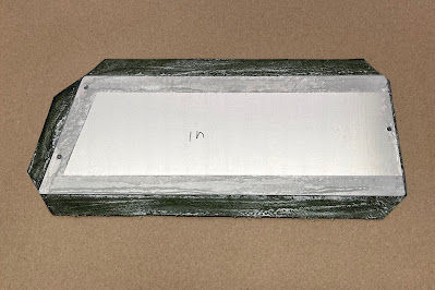
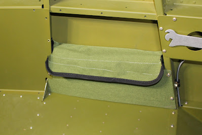
The year began with the creation of a pouch on the left side of the cockpit to hold the Ultimate Gust Lock. I obtained some extra seat fabric from Classic Aero Designs and made a pattern buck out of cardboard to simulate the shape of the pouch enclosure. An external panel was cut to shape and screw hole locations were determined. The aft hole would be matched to an existing nut plate in a bulkhead flange; two forward screw holes would require new nut plates to be installed in the next forward bulkhead. The panel was covered with a patch of fabric glued in place with contact cement; the screw hole openings were burned through the fabric with a hot nail, sealing the edges. The back side was masked before spraying the cement and the fabric flaps wrapped around the edges. Stitching the pouch would require skills and tools I didn't have, so I contacted Bill's Custom Canvas and they stitched up the pouch, adding some plastic panels to provide rigidity to the sides. I did a test fit and some modifications were required; Bill did them for free and also installed the snaps in the pouch flap. I determined how and where to attach the pouch to the panel; solid rivets wouldn't work so I used blind rivets with washers to secure the pouch and screws to secure the snaps to the panel. Once installed, the pouch fit well in the space and the gust lock fit snugly in the pouch. Job done.


I contacted my new DAR Matt Tomsheck and we discussed preparations for my airworthiness inspection. I opened an account with the FAA Airworthiness Certification Portal and began to fill out the required forms.

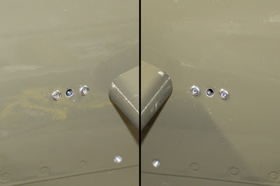
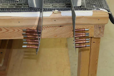
Then Amy and I got sick. It felt like a really bad cold; to play it safe we got tested for COVID. Turns out that it actually was a really bad cold that knocked us out of commission for over a week. When I was able, I got back to work. At this point I need to mention that working in an unheated hangar in winter really sucks, especially when the remaining fabrication required is on fiberglass fairings. I can't afford to invest in expensive heating systems right now; in any case, that would create condensation that would drip off the roof beams. I use a small tank-top propane radiant heater as a hand-warming station and bundle up as necessary, but when the hangar temperature drops well below freezing I can only stand to work a few hours at a time. I did a lot of running parts and tools back and forth from the hangar to the shop and back to the hangar just to try to get things done. I started with finishing the empennage fairings. The lower aluminum fairings were prepped and painted last fall; the bulk of the remaining work was done on the fiberglass upper fairing. The plans called for four nut plates to be installed in the aft end of the aft top skin that would hold down the forward ends of the upper and lower empennage fairings. I had neglected to install those nut plates prior to final assembly; installing them now would not be easy. I had match drilled the #30 pilot holes in the skin for the lower empennage fairing forward screws and it looked like I would be able to install nut plates with blind rivets if I could hold the nut plates in position with a magnet wand and capture them with a screw or clecos. I was hoping I could just use two nut plates to hold both fairings in place if the fiberglass upper fairing would overlap the aluminum lower fairings enough; initial fitting indicated it just might work. The upper fairing was sanded in the area that wrapped around the leading edge of the vertical stabilizer enough to allow a snug up to all three of the stabilizer leading edges. The forward holes were drilled first and clecos used to the upper and lower fairings to the aft top skins. From there I worked my way aft, pressing each side of the upper fairing firmly into place, match drilling the top edge screw holes and securing the fairing with clecos before following the same procedure to drill and secure the bottom edge screw holes. During this process I discovered that one nut plate along the edge of the left horizontal stabilizer had been mis-riveted. The forward rivet had missed the hole in the nut plate ear; the nut plate was misaligned and only held by one rivet. I drilled out the missed rivet and tried to swivel the nut plate into the correct position, but the fit still wasn't right. I ended up drilling out both rivets in order to properly realign the nut plate; the holes were reamed out to #30 in order to remount the nut plate with blind rivets as there was no room to squeeze or buck solid rivets with the empennage assembled. At least the problem was fixed. And by the way, the plans had called for K1000-06 nut plates for the empennage fairings. I had forgotten to double check the plans and had actually installed K1000-08 nut plates. Oh well; bigger is better than smaller, I guess; with the slightly larger hardware my tail will be an ounce or two heavier than stock.


The overall fit seemed acceptable but I wasn't happy with the way the fiberglass aft tabs fit behind the elevators. The plans called for the tabs to be screwed to the longerons behind the lower empennage fairings, but the fit was very sloppy. The fiberglass had warped slightly with age and the leading edges were curled outward so that they would catch the oncoming airstream. That seemed aerodynamically unacceptable and I pondered ways to modify the fit. I raised the tail of the aircraft and placed it on a jack stand for a better working position. The bottoms of the aft tabs were trimmed to fit even with the top of the longerons and I decided to fabricate attach plates that would form the tabs into shape and secure them to the longerons. Before I did that, I had to address the upper aft skin nut plates. The screw holes in the upper fairings were countersunk for flat head screws; the forward holes were ground enough to fit Tinnerman washers that would do the best job of holding the fiberglass securely in place. I considered using rivet nuts in the top skin screw holes but they were out of stock from my suppliers, so I decided to use standard K1000-08 nut plates. The screw holes in the aft top skin were final drilled to 5/16". I cut a screw head off an 8-32 screw and inserted the threaded shank into a nut plate. The shank was inserted in the screw holes to align the nut plate; #40 holes were match drilled in the skin for clecos. Then the nut plate ears and rivet holes were final drilled to #30 for blind rivets. Since trying to dimple the rivet holes skins with the tail assembled would be problematic, I chose to use domed head blind rivets and shape the fairings to fit around them. With Dave Pohl's assistance using the magnet wand, we were able to get the nut plates captured with clecos and riveted in place. The fairings were fitted with screws and the fit was nominal.


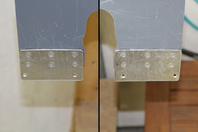
Measurements were taken and a cardboard template for the aft attach plates was created before the top fairing was removed and brought home to the shop. The attach plates were fabricated out of aluminum sheet; holes were drilled and the plates were brought to the hangar for dimpling and deburring. Back to the shop; the plates were clamped to the tabs and the rivet holes were match drilled to #30 for blind rivets. The screw hole countersinks along the lower edges were enlarged to improve the fit for Tinnerman washers. The tabs were secured to a drilling block with clecos and each hole was countersunk for flush blind rivets. Tabs and attach plates were prepped and cleaned, Pro Seal adhesive was applied and the plates were clamped and riveted together. After a few days of curing time in the warm shop, the top fairing was brought back to the shop and mounting screw holes were match drilled into the longerons and through the inspection covers. Due to a tooling swap error, the forward holes were tapped to 6-32 and the aft holes were tapped to 8-32; the forward holes were later re-tapped to 8-32 so that all the upper intersection holes would use the same size screws. The screw holes in the inspection covers were enlarged to 5/16" for clearance and that completed the empennage fairing fabrication for now. In the future the upper screw holes will be enlarged for Tinnerman washers, the upper fairing will be smoothed and all parts will be painted, but that will have to wait until spring. For now the parts are adequately airworthy for first flight.


Switching to the fuselage for a moment, I purchased and installed grip clips to hold the fuel tester in place above the pocket pouch. The existing pilot holes were reamed out to 5/16" for screw clearance and spare hardware was utilized to attach the clips. In the future I'll have to see if the edges of the clips catch on the clothing of a passenger, but for now it's a neat installation that should withstand aerobatics.
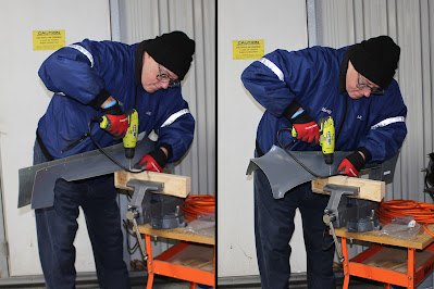
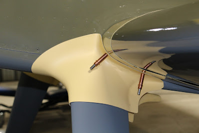
Now for the upper intersection fairings. Earlier test fitting revealed that the left one fit well and the right one did not. I removed some material from the interior of the upper leading edge, applied some pressure and heated the part with a heat gun to reform it into a better shape. My approach was to fit the outer halves of each part first. The inner halves would need to be relieved to fit around the larger Grove gear leg brackets and I wanted the outer halves to fit well before determining how to fit the inside halves. Pressing the parts in place against the wing fairings, I marked optimal outer mounting screw locations and drilled #30 pilot holes in the fairing flanges. Pressing the parts back into place again, the hole locations were transferred to the wing fairings, which were removed and pilot drilled. Fitting the intersection fairings to the wing fairings off the airframe revealed some misalignment, but the way the parts mated off the airframe didn't necessarily represent the actual finished fit when assembled. It's a common process when fitting fiberglass parts to have to sneak up on the correct fit; that method would definitely be required here. I determined good locations for the nut plates on the wing fairings first; it would be easy enough to modify and massage the fiberglass fairings to optimize the finished fit if necessary. The wing fairings marks were pilot drilled to #30; clecos held the nut plates in place while rivet holes were match drilled. I final drilled the screw holes to 5/16", dimpled the rivet holes and nut plate ears and riveted the nut plates in place. After reinstalling the wing fairings onto the wing roots, the first test assembly was done with clecos; the left one fit well but the right one was so far off that a second aft screw hole had to be drilled. Even with pressing the right side parts together, the fit was so distant that I had trouble engaging a cleco into the forward nut plate. I tried mounting the fairings with screws and once again the left one was good; the right one was miserable. Neither of the aft holes aligned well enough to start a screw; I had to ream the two holes together to form an oblong hole and use a Tinnerman washer to assemble the right intersection fairing to the wing fairing. At least the fiberglass can be easily repaired once the proper fit is set. I had to be careful not to cross-thread the forward screw as it was being pulled sideways by the poor fit. I wish I could order another right fairing from RVBits but I doubt it's possible to order just one fairing. In any case, having it shipped from South Africa nowadays could potentially take months. I'll just have to work with what I have and massage it into shape.


When the hangar temperature was too cold for fiberglass work, I sought out other tasks. I re-torqued the weeping coupling on the left gear leg brake line. The wing inspection covers and the gear leg pocket covers were also refitted.


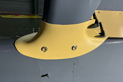
I chose to continue working on the left upper intersection fairing because I knew it would be the easier one to finish; lessons learned on the left side could then be applied to the right side. The next step was to determine where the gear leg bracket bolt heads contacted the inside of the fairing. I attached the upper half of the left intersection fairing to the wing fairing with screws and rubbed the bottom half against the bolt heads to leave contact marks. The part was removed; the marks were examined and pilot holes were drilled in the contact areas. The holes were reamed out and the part refit to the gear leg. By examining the bolt heads through the pilot holes, I determined where to remove more material so that the fairing bottom relief holes would fit around the heads. This took numerous fittings and resizing of the holes, but eventually the part fit nicely around the bolt heads and I was pleased to see that the gear leg bracket did not interfere with the fit of the bottom half against the fuselage bottom. I had considered riveting a nut plate to the inside of the gear leg pocket cover as another mounting point for the fairing, but I'm not sure I have the clearance for a nut plate to fit between the cover and the gear leg. Further investigation is warranted before any holes are drilled. With the fairing mounted, the final fit of the bottom half was determined and cleco clamps held the flanges together in the correct position. Thus fitted, the flange edges were no longer in alignment and trim lines were marked along the inside of the bottom flange. The part was removed from the gear leg; the flanges were realigned and clamped and #40 holes were drilled through the flanges in three places and secured with clecos. The excess flange material was trimmed and sanded off the bottom half to match the top half. I considered new methods of holding the flanges together that would be an improvement over the external nut plates used on the lower intersection fairings. I packed up the part and some tools and brought them back to the shop for further work. I'm considering molding an internal nut plate into the aft of the part that will fit inside the notch on the back side of the gear leg. It will be tricky to determine the optimal location and orientation. Internal hinges are used as closure devices on the stock gear leg fairings, but the curved shape of the gear fairing aft edges would pose a problem for hinges. I'm also wondering if Velcro might be used. There has to be a better way to close out the aft end of these fairings securely and with consistent alignment without incurring a drag penalty. I'm going to see what I can figure out.


I talked with Gus Warren about preparing for the first engine start. Gus is the President of EAA Chapter 194 at PTK; he is also the maintenance manager for the fleet of training and charter aircraft at DCT Aviation. We agreed that it would be best to wait until we had good weather and clear dry ramp surfaces before doing the first runup. Given the current weather patterns, that might keep me waiting for a while. Despite the internal urge to cross the finish line, I cannot rush this process; it has to be done safely and properly.
Since the approach to airworthiness has been slowed down a bit, I'm taking advantage of the opportunity to focus on other tasks, including the writing and publishing this blog entry. My trusty Canon Rebel SL5 has been in need of new batteries and a good cleaning so I took it to Billmeier Camera Shop in Fenton for some long overdue service. I expect it back sometime next week; I'll also buy a new camera bag as my old one is finally falling apart. My iPhone 13 will handle the substitute camera duties well enough for now. I'll be contacting a local Garmin expert sometime next week to plan my avionics calibration and determine what should be done before first engine start, prior to airworthiness inspection and after first flight. When the first engine run is completed, the fuel tanks will be drained and the plane will be fully assembled before weighing the aircraft and doing the weight and balance calculations. I've ordered two 15 gallon fuel storage jugs from Northern Tool, but so far only one has arrived. I've placed several calls to Northern Tool and expect to make more calls next week. My last flight was on December 14; I did some pattern work in the DCT Decathlon. That will likely be the last time I fly that particular aircraft. Any more tailwheel recurrency will likely be with Bruce Bohannon right before my first flight in my own plane. Flying with the Canadian Air Museum is still a possibility, but unlikely. The border is still open but COVID testing must be done and a lot of administrative preparations are required before traveling. I have a flight reservation scheduled for tomorrow in a Crosswinds Aviation DA40 to keep current and brush off some rust. It will be the last good weather window for flying for a while so I'm taking advantage of it.
The next post I make here will be momentous, for sure. First engine run; assembly for weight and balance; avionics calibration; disassembly for airworthiness inspection; reassembly and first flight; all lay ahead of me. What achievements will the next entry include? Will she finally be airworthy? When will she FLY? Stay Tuned!


