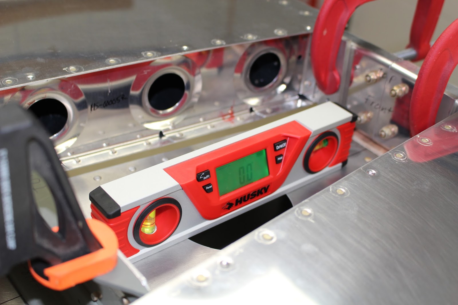
There were a few important tasks that got done before heading off to AirVenture. I removed all the painted cockpit panels, removed the wheels from the fuselage stand and replacing them with scissor jacks. I carefully leveled the fuselage before taking the big step of mounting the horizontal stabilizer to the fuselage for the first time. There is a lot of measuring and double checking in this process, making sure the stabilizer is centered, square and at zero incidence. Two spacers supplied in the kit needed to be finished and placed on the aft deck under the front spar; the rear spar needed to be spaced 3/16 up from the aft deck, and I had some plywood stock that neatly fit that requirement for jigging. One of the front spacers required a shim to level the stabilizer, which I fabricated from thin aluminum sheet. With the stabilizer clamped in place and all measurements and levels correct, I drilled the holes through the rear attach bars and the rear spar.


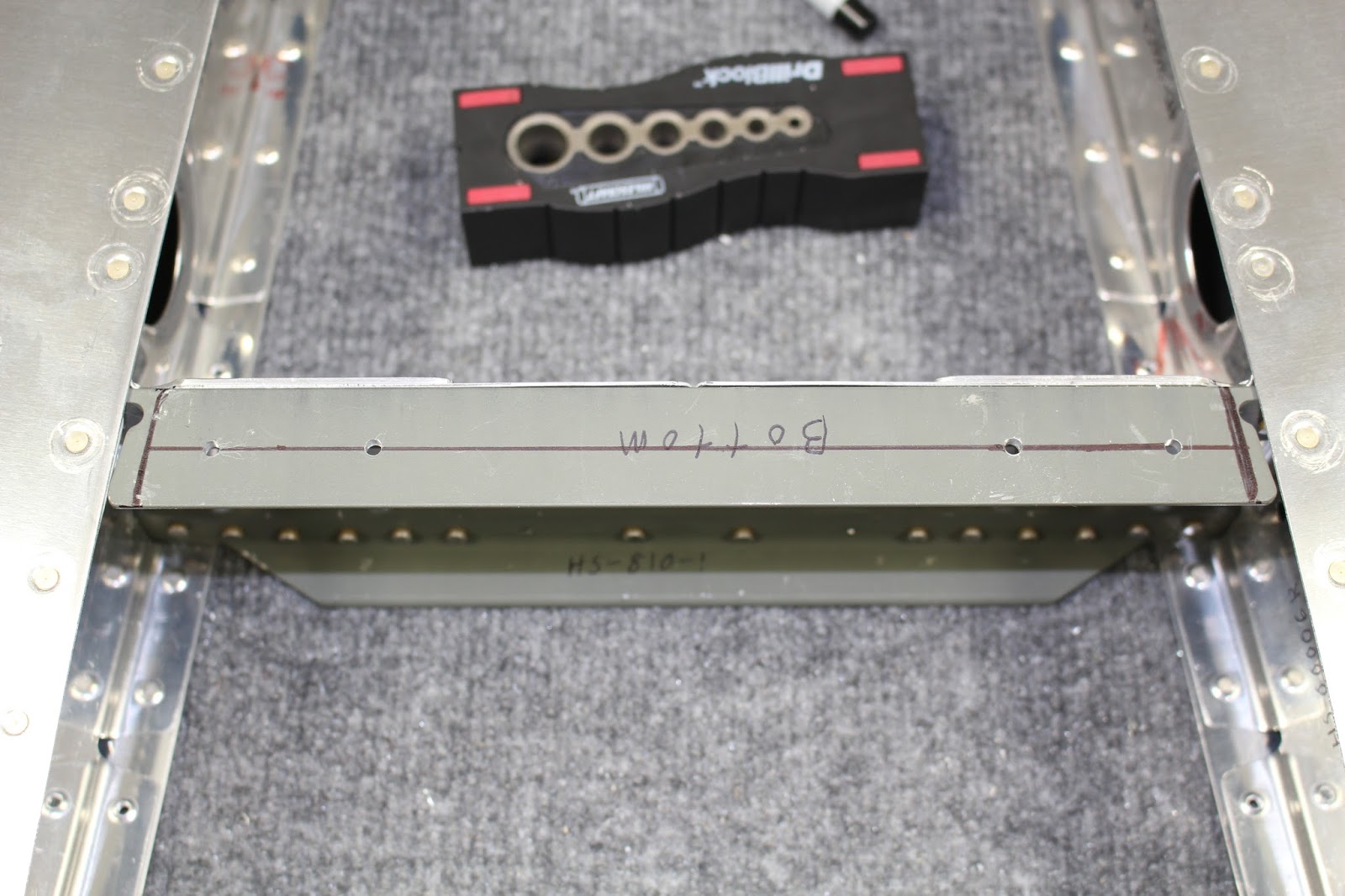
Drilling the mounting holes for the front spar was a bit more tricky. There were no guide holes in any of the parts, some of the holes needed to be drilled with an angle drill adaptor, and the spacing of these holes is very critical. I followed a technique used by other builders to make this just a bit easier. Rather than drill through all the parts at once with the angle drill hoping my holes would end up straight and in the right place through the fuselage longerons, I did as much measuring and double checking of placement while the horizontal stabilizer was on the aft deck. Then I removed the horizontal stabilizer and laid it upside down on the C-frame table so I could drill my own guide holes in the flange of the front spar, using the flat bottom surface to help me square up the hole. Even this was tricky because the flange wasn't wide or long enough to make the use of a guide block easy, and there was no way to maneuver this huge stabilizer safely onto a drill press table. I ended up making my own drill guide blocks out of hardwood and using them for the holes with tight access. I carefully marked and punched the hole locations on the flange and hand-spun a long drill bit to create a deep starting pocket for drilling each hole. Using the guide blocks meant that I couldn't see where the bit would be contacting the spar; I had to make sure I could feel that the tip of the bit was securely centered in the starting pocket. There was one close misstep while doing this, but I caught the misalignment before it became an issue. Lots of drilling, checking, drilling, checking... but when I was done I had four straight and correctly placed guide holes.


Clamping the horizontal stabilizer back onto the fuselage and repeatedly checking all measurements and levels, using the angle drill I match-drilled the four holes through the aft deck longerons and angles, then final-drilled the holes to the #12 size required for the bolts. I checked the placement of the holes with mirrors... and they were just right. Phew!


I completed this step the day before departing for OSH, and it was a great way to lead into the great time I had there (see previous post).


Upon my return, it was time to work on attaching the vertical stabilizer. I had previously refined the fit of the attach plate for the vertical stabilizer front spar where it nests into the back of the horizontal stabilizer front spar and clecoed it into place. Before I fitted the vertical stabilizer I knew I needed to trim the bottom of the front stabilizer to the correct length. The plans call for removing 9/16" off the bottom, but I knew of other builders that found out the hard way that they should have left more material for correct edge distance for the rivet holes. I played it safe by only trimming 1/2" off, smoothing the cut edge and then test-fitting the vertical stabilizer by clamping the bottom of the front spar to the attach plate with the spacer plate sandwiched in between, and using a cleco in the one guide hole provided in the vertical stabilizer rear spar where it attaches to the angle/control stop on the aft deck. Checking my measurements, this proved to be a wise decision.


Initial measurements showed that I wouldn't have room in the aft fuselage pocket to pivot the vertical stabilizer rear spar enough to make it square with the horizontal stabilizer. It wasn't off by much... but it was off, and I wanted it on. A call to Van's Builder Support provided a solution. That center guide hole I used to cleco the rear spar to the angle/control stop wasn't actually used in final assembly, so it could be abandoned. This would allow me to center the rear spar in the pocket and square up both stabilizers, but it would mean I wouldn't be able to use a cleco in that guide hole for jigging. I had to come up with a different method of clamping it in place until I could get some of the other holes match-drilled and clecoed. There was another guide hole in the bottom center of the spar that could be used as a guide hole for one of the three lowest bolt holes, but when I double checked the bolt pattern dimensions against the distances called for in the plans, something seemed very wrong. Another call to Van's confirmed this. The vertical distance between hole centers called out on the plans was 7/8", but the actual distance was 1-23/32". That made a lot more sense, but it surprised me that a known error like that would remain on the plans unmentioned. Again, Van's is not infallible, and it's up to a diligent builder to catch these things. Wasn't the first error... and it wouldn't be the last.


Once the bottom pilot hole in the rear spar was drilled through the aft fuselage bulkhead and tail spring mount, I was able to abandon the other guide hole, get the vertical stabilizer square and level and drill pilot holes for the other two lower bolt holes, then final-drill all three. Once they were deburred and temporarily bolted, all measurements were checked again and the upper two bolt holes could be match-drilled and final-drilled.


Now it was time to tackle the tricky task of drilling the rivet holes through the attach plate, spacer plate and front spar. Measurements had to be taken by running string to jigs attached to the rear spar and fuselage midpoints and/or the firewall and measuring the distance between the strings and the vertical stabilizer skin at set points, making sure the vertical stabilizer was true to the aircraft centerline. Then it had to be confirmed that the rear spar was very straight with no deflection fore or aft. There are a couple different ways of checking this; I used a thread strung through the mounting holes in all three pairs of rudder hinge brackets, making sure the taut thread was centered in all holes. Once it was certain that the vertical stabilizer was square, straight and centered, the front spar was firmly clamped to the attach plate and match-drilling the first guide hole through the spacer plate and front spar and securing it with a cleco. I double checked all measurements again before drilling a few more holes and putting in more clecos.


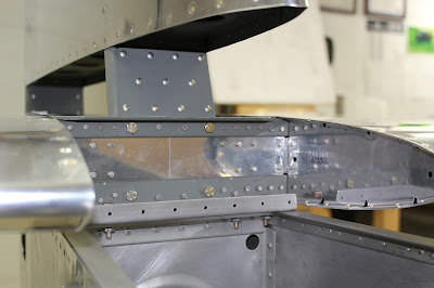
At this point the instructions would have you drill the rest of the rivet holes while the vertical stabilizer was still mounted to the fuselage and horizontal stabilizer, but that seemed way too awkward to me. Now that I had enough guide holes drilled that I knew clecos would properly center the parts, I removed the vertical stabilizer, attach plate and spacer plate from the fuselage and bench-mounted it in a way that would make it much easier to drill the remaining rivet holes. The attach plate was clecoed onto the back of the horizontal stabilizer front spar and the four holes were final-drilled to #12 for bolts. All holes were deburred in the attach plate, spacer plate and the front spars of both stabilizers. I prepped and primed the attach plate, spacer plate and the bottom of the vertical stabilizer front spar and riveted them all together. Now the vertical stabilizer could be temporarily bolted to the fuselage and horizontal stabilizer. Another big milestone.


Now it was time to work on control connections. I started by mounting the elevators on the horizontal stabilizer to check clearances. When the elevators are clamped in trail evenly the elevator horns don't line up perfectly, which is normal. The elevator horn that sits the most rearward gets the guide hole, so I removed the right elevator to lay out the first hole, remembering the mistakes of others and checking my dimensions many times and making sure I wasn't getting confused by the fact I was drilling from the back side of the horn. I had to make a weird table jig to support the right elevator horn while I drilled the pilot hole. I also had to make a hardwood guide block that would fit between the horns, and the odd size of the gap required a unique solution. I stock hardwood blocks for the jaws of my vise, and with the empennage kit Van's supplies an aluminum plate that serves as a bolt length and sizing guide. It turns out that the thickness of the plate combined with one of my blocks would add up to the perfect thickness for the guide block... and if I cut the corner out of the sizing plate that had the diameter gauge holes, I could use one of those holes as part of the guide. That was a stroke of luck that made drilling the left elevator horn much easier than expected, and I was pleased with the result.


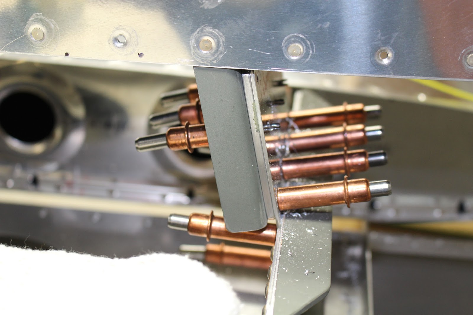
The next step was assembling the elevator pushrods and bellcrank. All pushrods are supposed to be primed on the inside. The ones with conical ends are easy, but the narrower ones with closed rod ends can't be primed once assembled. I decided to try something different this time and sprayed the inside of the narrow one with WD-40 before assembling it. This would serve a double benefit; it would lubricate the tube for the press-fit assembly of the ends, and WD-40 usually sets up to a gummy consistently that serves as a preservative coating. A good idea in theory... but inside the closed tube the WD-40 didn't set up as much as expected; I experienced oil leakage from the tube after it had been installed, which got oil on the pushrod exterior and the bottom of the fuselage. Hopefully this will clean up well and not give me huge headaches later when it comes to painting those parts.
Once all the bellcrank parts were smoothed, prepped, primed and assembled, it was time to work on the control column and sticks. The bushings for fore-aft movement of the sticks had to be filed down and profiled to fit the gap angle between the control column brackets. It took some experimenting to figure out the best assembly sequence for the control column, as well as attaching the pushrods to the bellcrank and elevator horns. I was surprised at how difficult these jobs turned out to be; very fiddly and very frustrating at times, especially dealing with multiple washers in confined spaces. I used the trick of using sticky grease to stick the washers together for insertion into the gaps between rod end bearings and attach flanges. That helped a lot... but still a pain. Once I had the sticks connected to the elevators, I realized I needed to shorten the front stick to clear the instrument panel angle and get the full available travel out of the elevator. I took some measurements with my digital level and realized that some filing of the aft control stop angle would be required to get the travel into the correct range. Before I did that, I fitted the rudder and checked the fit. With the rear spar running true, some adjustment of the rod ends was required to regain proper fit of the bolts through the brackets and rod end bearings. Then I filed the rudder control stops to get the right amount of available travel left and right. I removed the rudder and started the filing of the aft control stop for the elevators. Wanting to be careful, I did all the filing by hand and it took a long time to remove a fair amount of material. Because the horns weren't exactly parallel, the filed relief in the aft control stop angle was skewed slightly to assure that both horns would contact the control stop at the same time. The finished stop doesn't look pretty... but the elevator travel is within the correct limits, and that's more important.


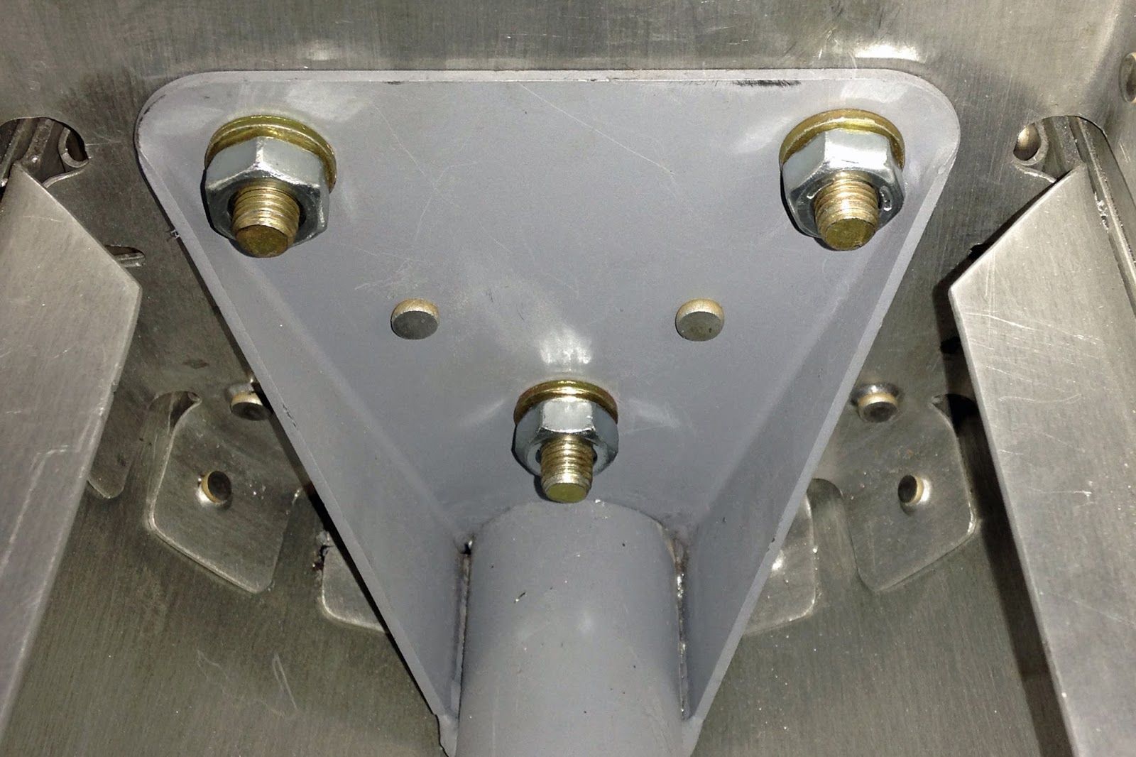
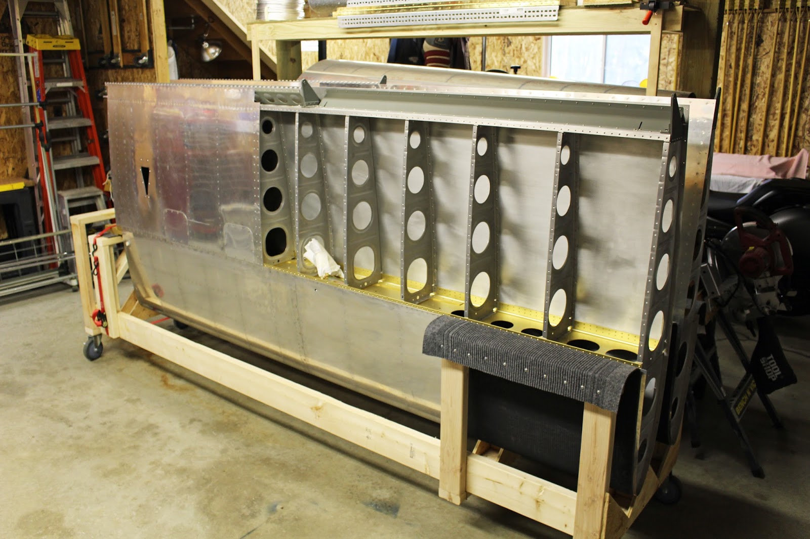
At this point I decided I should backtrack and get the landing gear dialed in; it was one of the jobs that was set aside because at the time I couldn't get the assistance to flip the fuselage upside down. But I didn't want to get too far down the road and make the job more difficult with more parts installed and increased weight. I got a few friends to visit and help me with the quick and easy job of flipping the fuselage from the rolling stand to the folding workstands. After checking the level, I got to work match-drilling the inboard wear plates, using the Grove inboard brackets as a drill guide. I had to jig the parts together and bolt them to a wood block to make sure correct alignment was maintained. Bolting the gear legs to the fuselage is another task that gets very complicated when done by myself. Having a helper hold a leg while I bolted it would have been easy, but I had to get out the cherry picker and figure out how to safely suspend each leg in place while I got the bolt through, secured a wrench on the top side and tightened from a creeper underneath the fuselage. I ran several loops of string through the axle attach holes and hung that end from the cherry picker until the main pivot bolt was in place. Fiddly and time consuming, but I got it done. The alignment process for the Grove airfoil gear legs is a bit different from the stock gear. Instead of hanging plumb bobs from strings and comparing from other measuring points, I used the parallel angle method of fabricating two alignment jigs from 4' aluminum channels and bolting them to the axle attach holes, making sure they were level fore and aft. Then I measured the distance between the front ends of the jigs and the back ends and made adjustments until they were the same value for zero toe in/toe out. Then I had to measure from the front bottom of each gear leg to a centerline marked on the tail spring mount, making adjustments until they were the same value for straight and centered alignment. If any adjustments to either toe-in or alignment had to be made, all measurements had to be rechecked until alignment and toe-in were both correct.


Once that was done I could start working with the outboard brackets and determine how much fuselage skin needed to be trimmed away for the brackets to be fitted. The Grove airfoil gear are made from aluminum and need to be thicker than the stock gear legs, so Grove supplies their own larger brackets. The inboard brackets still fit fine, but the outboard brackets require significant notches to be cut in the skins on either side of the gear locations. The gear cover plates must also be trimmed back to clear the outboard brackets. I did the initial layout and trimming with the legs in place, but needed to remove the legs in order to smooth and deburr the edges. Then remount the gear, check clearances, remove gear and touch up edges, then remount gear to check again. As I said, a simple task for two; a complicated time-consuming task for one, but it got done.


After I was certain I had the right clearances to allow me to set proper alignment, the gear stayed on and I reset the alignment. I called Van's Builder Support to confirm the accuracy of the non-stock alignment method before drilling the required holes for the outboard and inboard brackets that would set the alignment. These had to be drilled accurately through multiple layers of aluminum and steel weldments that had no guide holes. The brackets and wear plates had to be correctly placed according to the measurements on the plans, then the assemblies secured by tightening the main gear pivot bolt. The brackets would serve as drill guides to drill the large holes to size in one shot. I took no chances and got brand new cobalt bits to drill all the required holes for the inner and outer brackets and wear plates, and it went well. I inspected the drilled holes and they were all correctly placed through the skins, angles and weldments. Drilling the outer holes for the outboard wear plates was tricky, but with the brackets and wear plates bolted, the guide holes that are already done in the fuselage skins and outboard wear plates made it easy to keep the correct alignment of the drill bit, and that went smoother than expected. Then it was time to remove the gear, deburr all holes and flip the fuselage upright again.


With the fuselage upright again it was time to reattach the empennage, control column and pushrods and work on control connections again. I test fit the flap actuator after reaming the powdercoating out of the bracket and weldment bolt holes. This assembly also proved to be much more fiddly than expected. I'm given the impression that the more I get into this build, the more difficult the little tasks will become as the assembly becomes more complicated. This results in my jumping between given tasks for various reasons. The procedures I describe here may not be listed in accurate chronological order; I will defer to my KitLog Pro builders log for that. In this blog I will tend to group tasks by type of work to make it easier to follow through a particular assembly.
The ground-adjustable rudder pedal option that I chose for my aircraft is simpler, cheaper and lighter than the inflight-adjustable setup. But the popularity of the inflight-adjustable setup has made it the stock configuration, and the ground-adjustable setup is now an option with its own blueprints and instructions. One of the first instructions was to drill out two round head rivets securing angles at the front of the gear towers and replace them with flush blind rivets. Because the angle flange interfered with the head of the rivet puller, this was tricky; I had to come up with a way to shim the rivet mandrel enough to clear the flange without compromising the grip of the puller. Using the same piece of template I used in drilling the elevator horns, I drilled a hole to allow its use as a shim, along with a pair of small nuts, and got the flush blind rivets set properly.

The rudder pedal attach angles are set over these and secured with their own blind rivets, 14 total on each attach angle. I followed the drawing specs, marking and drilling #40 pilot holes along each attach angle. The drawings seemed to indicate that there would be enough room to set the end rivets in their own holes with proper edge distance from existing rivets, but the reality was that the aftmost blind rivet holes would end up right over the flush blind rivets I had just set. Based on the required dimensions called out in the plans, I made a template out of some scrap angle, and my suspicions were confirmed.

Another call to Van's Builder Support led me to the conclusion that I'd have to drill out the flush blind rivets I'd taken so much care to set properly. Oh well; that's better than setting rivets too close together. The larger blind rivets required at each end required bigger holes to be drilled which would compensate for any slight misalignment of the smaller holes. I started by knocking out the set mandrels in the flush blind rivets and drilling #40 holes so that I could use clecos to pin the attach angles down and double check measurements before final-drilling. The rivets on the forward ends would also be a little problematic, but there was enough working room on the preinstalled firewall angles to find a suitable location for the forward end rivets for the attach angles. Once I was assured the layout would work, I match-drilled most of the floor holes using the hole pattern I'd established on each attach angle. For the forward ends, I had to put paint on the tops of the existing rivets and then cleco the attach angles down so that the paint would mark the bottom of each attach angle. This would tell me how much material would have to be relieved to prevent any interference. Once that had been established I could determine the best place to put the forward rivet holes. After all these little details were worked out, I relieved the forward ends, got the forward rivet holes pilot drilled, clecoed the attach angles to the floor and match-drilled all the holes to their correct sizes. The fit was checked with the rudder pedals bolted in place, then the attach angles were removed, deburred, prepped and primed. Eventually they were riveted in place with the appropriate round head blind rivets, using the same technique I had used to set the original two flush blind rivets. Not all mandrels cooperated with the shim technique and a couple had to be cut off at the top of the rivet head after setting. But the job got done.


Another required fabrication was of two triangular thrust washers that fit between the rudder axle flanges and the rudder pedals. The thrust washers were made from UHMW polyethylene squares whose properties were ideal for the application but required special drilling and cutting techniques. I wasn't happy with the first pair I made, so I bought some larger squares of replacement material from my local plastics distributor, refined my fabrication techniques and my second pair turned out much better.


It took a lot of filing and finish sanding to get a proper assembly fit on the rudder pedals, axles and brake cylinder arm tubes. Once I was happy with the spacing, fit and action of the pedals on the axles, the bolt holes were finish-drilled to size, the bolts inserted and torqued to spec. After getting the attach angle issues resolved and getting them trimmed, prepped and primed, I attached the rudder and brake pedal assemblies, clecoed them in place and reassembled the cockpit floors and front seat components so I could sit and check the fit before I riveted the attach angles. This was my first opportunity to sit on the custom seat cushions from Classic Aero Designs, which had arrived at the beginning of the month. It also presented an opportunity to test another assembly technique I had been pondering. The floor stiffeners on the forward part of the left and right floors should not be riveted in place until the floor is ready to be permanently attached to the floor ribs with blind rivets, because the floor skins have to be flexed to be fitted in place. Riveting the three forward stiffeners on each floor skin is going to be difficult because of the awkward access, reaching underneath from the front with a bucking bar. It would be difficult to even get the parts clecoed into place. I wondered if the stiffeners could be held in place with two rivets before fitting; would this allow enough flex to fit the floor skins? I tested the theory using two clecos in the outboard rivet holes securing each stiffener to the floors; fitting the skins in place was no problem. So I removed the skins, set rivets where the clecos had been holding each stiffener, and refit the floors including the front floor and seat angle components. I put the front seatback and cushions in place and climbed into the fuselage. It was cool to sit in the cockpit with the seats, sticks and rudder pedals in place; it gave me a better sense of how I'd wear this airplane. I may end up bending angles in the stick as some other builders have done; I won't know for sure until I get my Tosten grip from Aerotronics. But I think this aircraft will be a good fit on me.


Satisfied with the control placement, I disassembled the cockpit seat and flooring and worked on the brake pedals, drilling the master cylinder attachment holes and deburring the pedals. I assembled the rudder pedals, brake pedals and attach angles and clecoed them in place on the floor. I attached the cable linkages to the pedal assemblies and rudder horns and checked the action of the rudder and pedals. Some massaging of the brake cylinder arms was required to get enough arc in the pedals to allow full rudder travel. Once that was established, the rudder pedals and axles were cleaned up, lubricated and assembled. After one last test fit with clecos, everything was disassembled again and the attach angles were prepped, primed and riveted to the floor as described earlier.


I had to decide where to proceed from here. Fall has arrived; winter will soon follow and I really want to get the fuselage interior sections painted before it gets too cold. I removed the empennage and control components again and stored them in the garage bays, where I also moved the wings. I turned the fuselage around in the shop so that the cockpit was facing the shop garage door and started some of the prep work for interior paint. I fitted the NACA vent to the fuselage. The Garmin pitch servo brackets required some modifications to bulkhead flanges, a mounting bolt hole had to be drilled in the bellcrank and rivet holes needed to be laid out and drilled in the brackets. When I saw how the rivet holes lined up with the floor ribs, I wasn't real happy... but I thought I could make them work and committed to the placement by match-drilling the holes. They will have to be primed before riveting.


I ordered some brake pedal extensions and some roll bar handles from online sources, and they've arrived. I also had the Grove landing gear brackets powdercoated to match the Van's wear plates. The finish kit has been ordered and should be shipped within the next two months. I'm also putting together a financial plan to get the engine and prop ordered soon.
There are a lot of different thing that need to happen next. I will have to put a door into the north side doorway of the woodshop that can be fitted with a ventilation fan. The large paint booth needs to be reconstructed. The fuselage will require a lot of cleaning and masking before painting. I may have to investigate propane torpedo heaters to heat incoming air to the paint booth. Now that the control configuration of the empennage is mostly complete, I could begin fiberglass work on those components and get them ready to paint. All this and more will be covered in the next post; stay tuned.