There is a common analogy among homebuilders that building an airplane is like climbing a mountain. It's a long and often difficult journey; there are many peaks to scale and many valleys to cross. For a first time builder, finishing the cowling is one of the more daunting ascents, with a lot of twists, turns and detours. Lots of time spent on the climb so far, and there's still a long ways to go. This will be a long entry; there's a lot of ground to cover, so let's get going.
But first, a detour: I got a nasty surprise right after posting the previous post. Fellow builder and VAF member Chris had noticed in my photos that I had routed my rudder cables incorrectly through the spar box. This induced some panic in me, because I was certain that at this late stage rerouting would be problematic at the very least. I expected to find that I had drilled out the pilot holes I should have used for the cables and routed wires through them, and the thought of having to change wire routing made me nauseous. But upon inspection I found the pilot holes were unused; there were no obstructions anywhere and disconnecting the cables was far easier than expected. The holes were drilled out; snap bushings installed; the cables were rerouted and reconnected. It turned out to be a fairly easy fix, and an immense relief. It also explained why the cables had been chafing the landing gear towers when I had installed them without the rudder extension pivots.


The next big job would be finishing the cowling, but the fuselage needed to be level to do that work. Rather than use stands, I decided to try something different. I fabricated a tailwheel pocket stand and mounted it to the shop wall. It took several tries to get the stand mounted at the right height; a rag was used as shim material. The left main wheel also had to be placed on wood shims to level the fuselage. The tailwheel was secured to the wall stand with zip ties; I also applied tie-down straps as an additional safety measure.


To make sure the cowling is centered properly on the propeller, many builders install just the spinner backing plate or a round wooden template on the engine to aid in alignment. That makes it easier to work on the cowling without the prop in the way. The spinner for my Whirl Wind RV200 constant speed prop has a two-piece backing plate that mounts to the prop instead of the crankshaft. The Whirl Wind prop also does not use a prop extension; as a result, the two piece backing plate has a conical design that would be difficult to duplicate accurately with a template. I had to install the prop in order to mount the spinner and get the cowling placed correctly. Fitting the prop should have been fairly simple, but of course it wasn't. The spinner mounts onto a two-piece spinner mounting plate that is held together with temporary spinner installation plates while the prop is fitted; the installation plates are removed once the prop is bolted onto the crankshaft. I fitted the prop with the spinner mounting and installation plates in place; the plate bolts were inserted from the aft side of the plates, per the instructions. The installation plates must be bolted in place to align the mounting plates prior to tightening the prop bolts, which will then hold the alignment while the bolts and installation plates are removed and the spinner backing plates installed. But there was a problem: with the prop bolts cinched down, there was no way to remove the bolts. There wasn't enough clearance between the spinner mounting plates and the ring gear to get the bolts out of the holes. It was a classic Catch-22. the bolts had to be in to hold the initial alignment, but couldn't be removed after the installation. If the prop was loosened enough to remove the bolts, then the alignment of the spinner mounting plates would be lost when the installation plates were removed. I did some research on the VAF website and called Whirl Wind to discuss the issue. I spoke with Jeremy at length and we decided the bolts would have to be installed from the front, facing aft, instead of the orientation described in the instructions. He also gave me some important additional advice that was not described in the instructions on propeller installation:
1. Leave spinner off for first engine run. Torque prop bolt (actually a stud/bolt/roll pin assembly) to spec, but do not safety wire yet. If the engine/prop is vibrating from imbalance, it may be necessary to re-clock the prop 180 degrees to see if that helps prior to dynamic balancing.2. Clearance issues while applying safety wire to the prop bolt may require that the bolt be loosened slightly to run the safety wire, then re-torque to spec. Don't safety wire until after the first engine run and the installation is permanent.
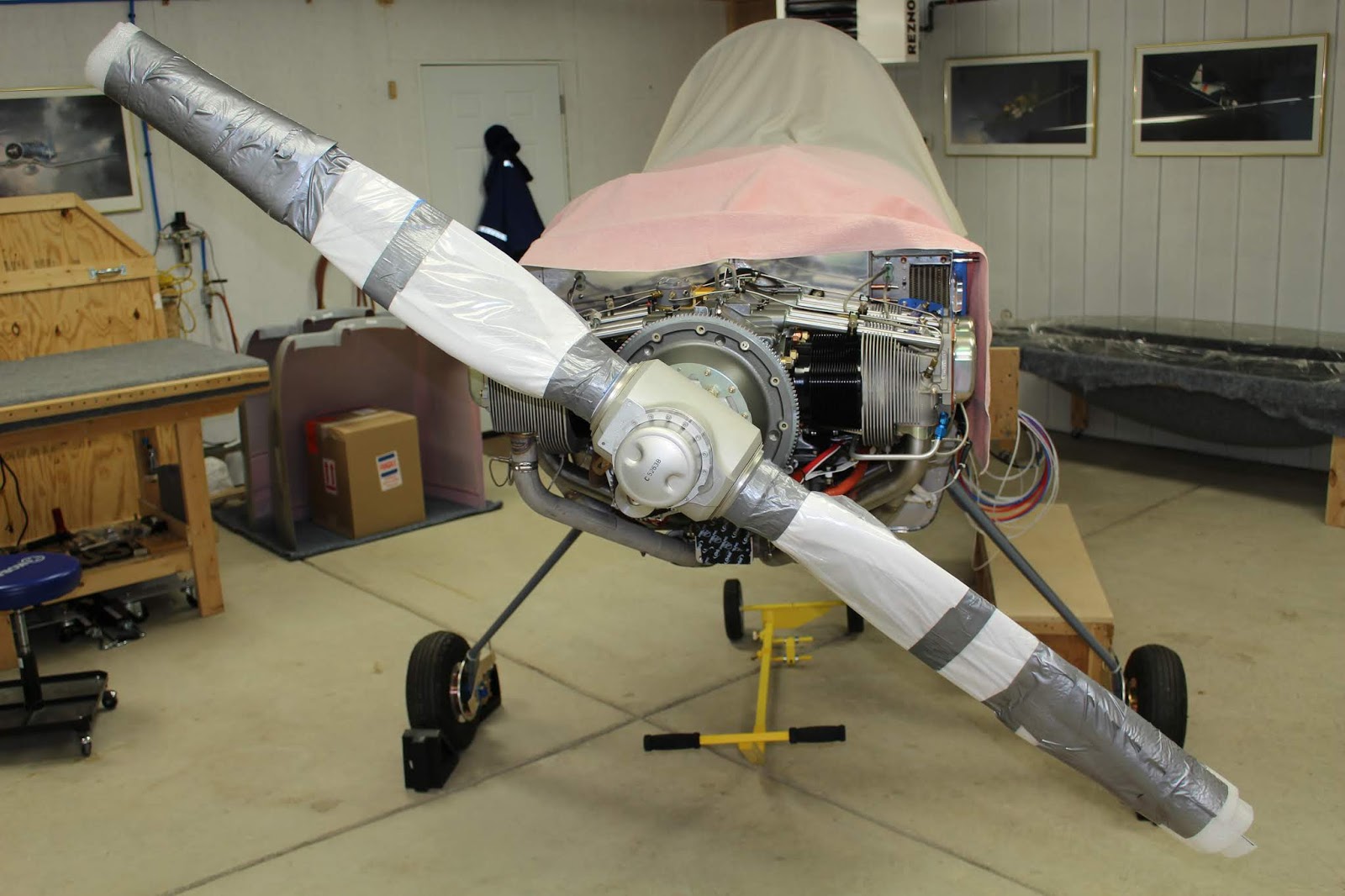
3. PROTECT PROP BLADES VERY WELL! The trailing edges of the composite prop are very susceptible to nicks from dropped tools during assembly. Wrap the props very carefully with padding to prevent any damage until just before running the engine.


Fitting the cowling is a big job, and I spent a lot of time doing research and planning the best way for me to approach it. The front baggage door was taped in place on the fuselage to set the alignment of the firewall flanges. Some additional cut line layout was done on the baffles before they were removed. Based on the advice of other builders (especially Dan Horton) I determined what I would need, and where to start. I fabricated two brackets that would bolt on to the front cylinders that would support the top cowl during fitting. A jig was made that would hold the correct aft spacing of the cowling halves. Although I wasn't able to use a circular wooden template as an alignment jig bolted to the crankshaft, I would still need one to help align the nose bowl of the cowling, so I cut a 13" circle out of particle board. Using woodworking techniques found on the internet, I trimmed it as round as possible with the table saw. I assembled a cowl opening alignment tool using aluminum angle, square tube segments and flat stock and attached it to the wood circle with one edge of the angle bisecting the circle. This would me determine where my first trim lines would be on the top cowling. After doing a lot of double checking of measurements, the first trim cuts were done on the top cowl nose flanges and the edges evened and smoothed with sandpaper on long straight edges.


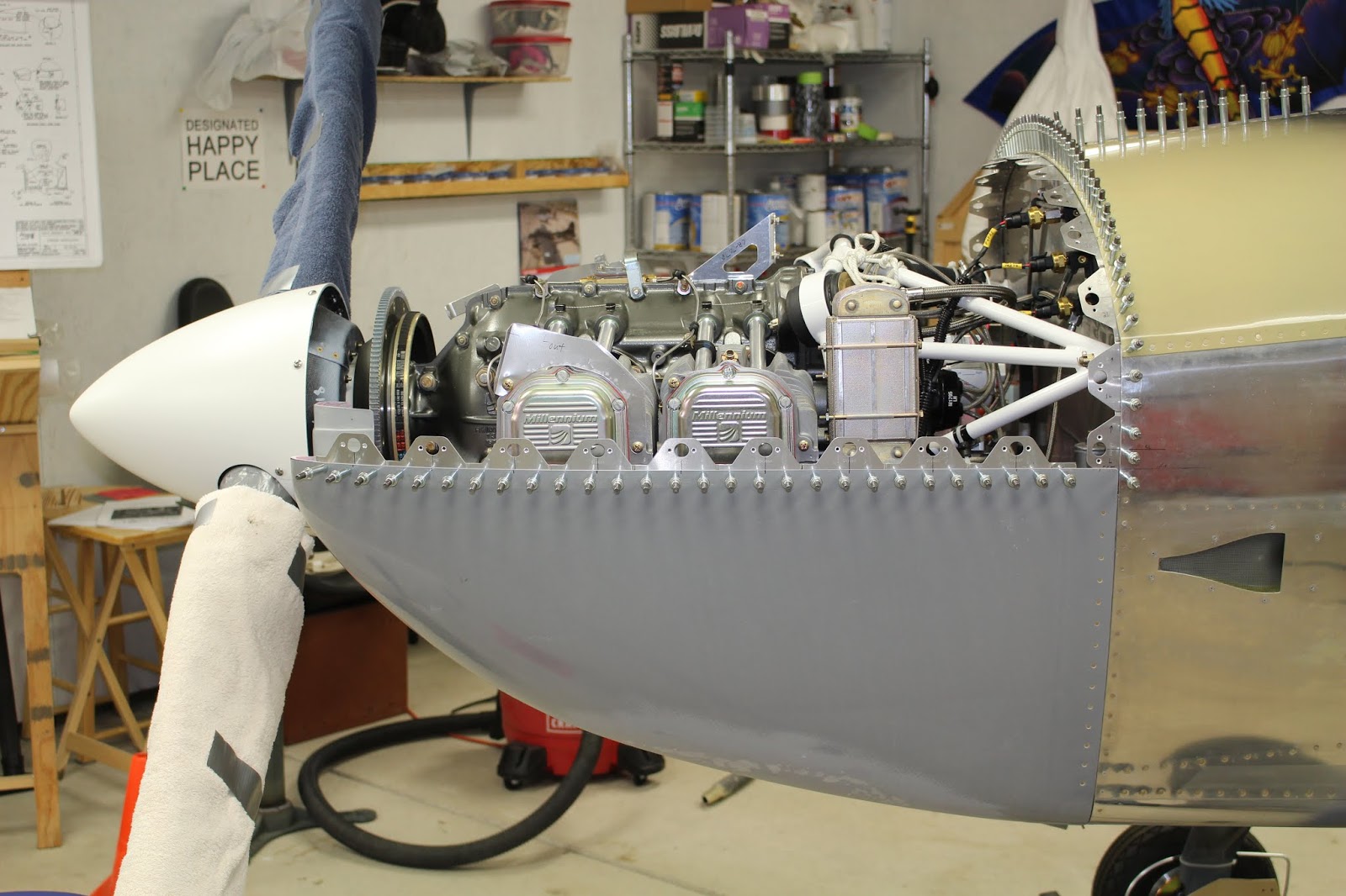
With the first trim done, the top cowl was placed on the fuselage and support brackets. It took numerous trims to get the brackets to the right height so that the top cowl would align properly with the spinner. Builders are often told to compensate for future engine sag when building in the cowling alignment. Since my engine was hung many months ago I'm hoping that most of the settling of the engine mounts has already occurred, although the first engine runs might cause a bit more. My alignment will take that into account. A laser level was used to check the lateral level. The support brackets were trimmed (and a small sub-bracket added) until the top cowl sat level side-to-side.


The aft trim line of the top cowl could now be established. 2" PVC tape had been laid down along the forward edge of the top skin around the firewall. A center line was marked the top forward skin; the top cowl was centered at the front and a 1/8" thick piece of aluminum angle was used as a shim to set the distance between the cowl nose and the spinner. After checking the front of the top cowl with a laser level, a second piece of 2" PVC tape was laid down along the aft edge of the top cowl, precisely aligned with the tape below. This effectively set the layout for the trim line of the aft edge of the top cowl; the line was marked with a sharpie and the top cowl was removed. The bottom cowl was checked to see if the molded-in joggles at the nose were accurately placed for centering the bottom cowl, using the nose alignment jig and a straightedge. Marked a potential cut line on the outer nose of the bottom cowl, then test fit the bottom and top cowls together and double checked all alignment edges. Before doing any more cutting, all building resources were reviewed to make sure these steps were being done properly. The center line was extended on the top forward skin and marked with fine line tape; three temporary support strips were fabricated and clecoed to the firewall and top forward skin. The first trim cuts were made on the bottom cowl; the overlapped sections of the nose were trimmed to mate evenly with the top cowl cuts and the fit of the spinner bowl was checked.


A couple side tasks were done next. The right temporary support bracket had to have a small extension fabricated out of aluminum angle to get the cowl height set correctly. This had been held in place with cleco clamps; when I was certain that it was clamped in the right place I match drilled #40 holes through the angle and support bracket. The parts were clecoed together and the cleco clamps removed; later on the parts would be riveted together. During this phase of the fabrication, I noticed that a small kink had been created in the top forward skin and baggage door support strip, adjacent to the top of the baggage door opening. It was probably caused during handling, as that section of metal is relatively narrow and otherwise unsupported. The kink wasn't serious, but it was noticeable and it further enabled the tendency of the firewall to bow away from the front edge of the baggage door. With everything carefully secured in place with tape, clecos and support strips, I was able to gently squeeze the kink out using a C-clamp and a chunk of vinyl cutting block.


I cut the aft edge of top cowl, smoothed and straightened the edges and checked the fit on the fuselage several times, sanding and fitting until I was satisfied that I had a decent initial shape that could be refined as needed.


With the top cowl in place, centered and level, I used the laser level to set the horizontal trim lines on the bottom edge of the top cowl and marked the lines with fine line tape. I double checked everything, took a deep breath and trimmed the bottom horizontal edge of the top cowl, smoothing the edge with long straightedges and sandpaper. The aft right corner trim left a little bit of the original edge, angling up slightly. For now that would stay; I trusted the level of my initial cut and I knew that further fitting was bound to occur.


Van's stock design uses piano hinges to secure the cowling to the fuselage and tie the halves together. These work just fine but the hinge pins can be difficult to remove at times, especially when the engine is hot. Many Van's aircraft builders have chosen to use Camloc-style studs and receptacles supplied by Skybolt Aerospace Fasteners to secure their cowlings. Based on the recommendations of builders I know personally, I decided that I would use Skybolt fasteners for my top cowl and the stock hinges for the bottom cowl along the firewall. They make it much easier to remove the top cowl, and with the top cowl off it's easy to remove the bottom cowl hinge pins. Another plus is that the Skybolt fasteners would add to the military style of my aircraft. Installing this hardware on the cowling is quite a bit more involved than installing hinges, and requires a lot more effort to get right. I'm told the extra effort is worth it. More on that later... probably much later.
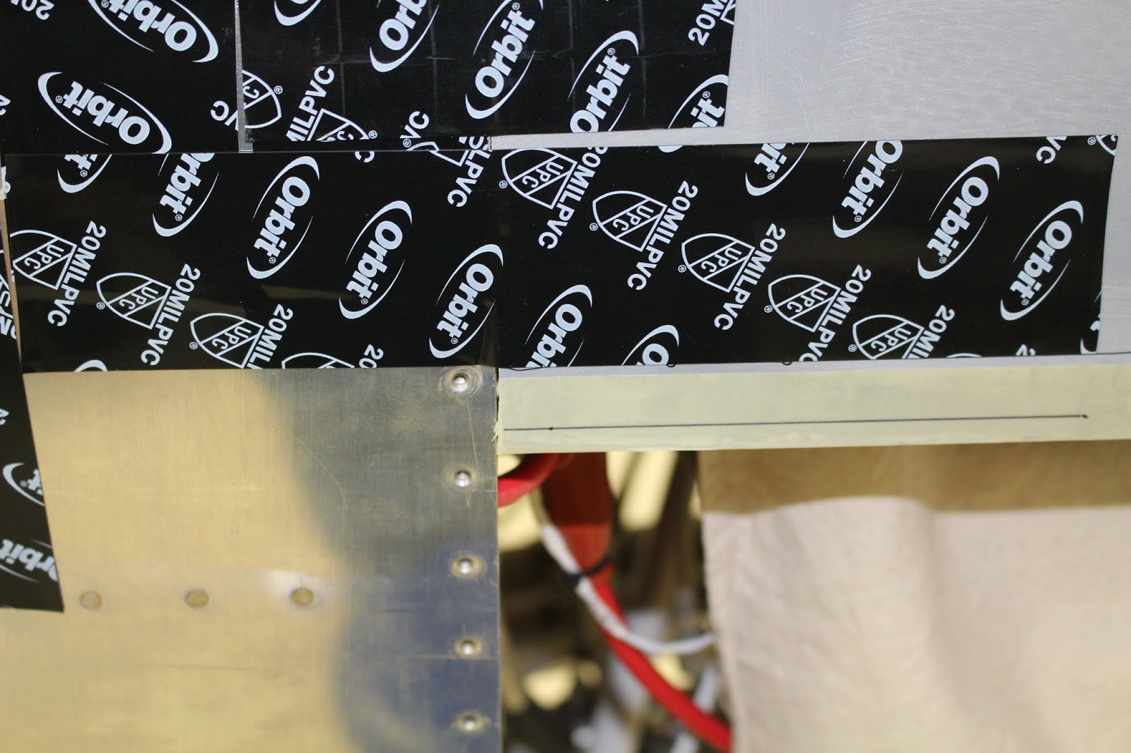
Skybolt supplies a number of flange sections that are riveted to the firewall and along the top edge of the bottom cowling. The Camloc studs engage receptacles which are riveted to the flanges. The first step in the installation process was to determine the center line of the Camloc studs along the horizontal edge of the top cowl. Skybolt recommends a nominal spacing of 3.5" between studs; the spacing can be shortened to allow proper centering of layout. It is desirable to have the aft bottom corner stud on each side to be centered on both the vertical and horizontal row lines; the spacing will extend forward and upward from each one. Symmetry isn't as critical for each side; after all, the cowling is molded asymmetrically to accommodate the offset of right and left cylinders, and it's impossible to see both sides at once. But symmetry is desired along the firewall lines, so the center line and end points should both be taken into consideration. Some builders choose to place a stud on the center line at the top of the firewall, but I determined that I would get a more secure fit if I flanked the center line with two closely spaced studs. That gave me seven studs on each side of the center line and would help eliminate the pucker that can occur between studs in flight; more on that later. Skybolt recommended that the flanges be mounted so that the cowling edge is .230 to .250 below the top of the horizontal tabs that form the base of the flange. The receptacle rivet holes can be used to layout the center lines of the studs. My bottom corner stud would be actually mounted on a firewall flange; all subsequent horizontal flanges would be spaced 3.5" forward from there. But to make it easier to start the layout in the right place, I taped a flange on the horizontal line for reference as seen in the photos.


There are a couple of issues with the firewall edges that have to be dealt with. On the RV-8 there is a slight change of relative direction where the top forward skin overlaps the side fuselage skin. There are also different thicknesses of the firewall flange; along the forward top skin it is three layers (skin, baggage door support strip and firewall flanges); four layers where the top and side skins overlap, and only two layers along the sides (side skin and firewall flanges). To help offset these differences, I had to make up two short shims that would bring the lower sides out to the same thickness as the upper sides. The slight change in edge direction was easy to compensate for with the interlocking flanges; they just needed to be laid out in a way that could accommodate it. The Skybolt flanges are stamped and punched with the overlap joggle prefabricated, but the rivet holes need to be machine countersunk and any additional forming to contour must be done by hand. The flanges for the bottom corners adjacent to the cowling split are fabricated first (labeled FSF-R and FSF-L) and subsequent flanges working upward would be fabricated in such a way that both the intended layout and rivet hole spacing (dictated by the existing holes in the firewall flange) would work out. In my case, I would be riveting hinges along the firewall below the split. I fabricated each firewall flange individually, labeling them numerically from bottom to top and left/right. They were bent to shape, modified as required, match drilled to the firewall flange and clecoed in place. Countersinking and deburring would come later.


With the flanges laid out, I could now fabricate the hinge sections that would secure the bottom cowl. I cut four sections; two longer ones for the sides and two shorter ones for the bottom. There were temporary rivets that needed to be removed, and new rivets that needed to be squeezed along the bottom outer curves of the firewall flange and the inner vertical flange along the exhaust pocket. The hinge halves for the firewall flange were clamped in place and match-drilled to the existing rivet holes, inserting clecos as I went. After all the firewall flange hinges were drilled, they were removed and placed on a jig board for machine countersinking before being clecoed back on to the firewall flange. On the same jig board, I fabricated a jig to hold the Skybolt flanges in place for countersinking the #30 holes for riveting the receptacles in place. The firewall flanges were removed, machine countersunk, deburred and clecoed back in place.


Switching back to the cowl halves, I began the long, drawn out task of fitting the front of the cowlings to nest together properly. There were areas along the inside edges of the intake flanges that had excessive material built up; these were sanded down with a Dremel barrel sanding bit and smoothed with files and sandpaper. The mating area along the top edge was cut out a bit more along the horizontal edge to improve nesting prior to trimming the bottom cowl. I drilled two temporary cleco holes through the overlapping nose bowl flanges to help hold them in place during fitting to the fuselage. The top cowl was put on the fuselage, shimmed and taped in place. The hinges were clecoed to the firewall with the forward hinge halves installed with the hinge pins Then the bottom cowling was fit to the fuselage for the first time, strapped in place with the bottom cowl edges tucked underneath the edges of the top cowl. The 2" tape trick was used again to set the trim line for the aft edge of the bottom cowl and the finished top cowl edge set the bottom cowl trim line. The bottom cowl was removed, secured to the work table and the edges were trimmed and sanded. This was repeated a couple times until I was happy with the fit. It was starting to look more and more like a real airplane.


I marked layout lines on the remaining flanges and countersunk their #30 holes. The cowling was removed again and some more baffle planning done. I removed the temporary support brackets, reinstalled the side baffles and overlaid the support brackets on them to give me an idea of where the underside of the top cowling would be. The side baffles were marked and removed; the support brackets were reinstalled. More edge sanding was done on both cowling halves and more test fitting done. The Skybolt flanges were mocked into place along the top edge of the bottom cowling to get a better sense of the required layout. I built up a support platform for the nose of the bottom cowl to assist in temporary fitting made up from a sawhorse and a hinged carpeted platform that was intended for a tail stand that was never completed.


Marking the layout for the forward hinge halves would be a challenge. With the bottom cowl in place it was difficult to reach inside to mark the outline of the hinge on the bottom cowl; I could only mark a few places and hope that it would suffice. The hinges come with their own aluminum hinge pins; these pins are replaced with stronger stainless steel pins that are cut to required length. During this process I discovered another problem. The bottom hinge pins are supposed to be inserted from the inside of the exhaust pocket and secured to the inner bottom vertical firewall flanges. But with the Vetterman four-pipe exhaust installed, there was no room to get the pins inserted from the inside. Even if I cut the hinges a bit shorter, the pins would have to be flexed so severely that it would either bend the pins or the hinge tabs. It became obvious that the pins would have to be inserted from the outside. This would require an access notch be cut into the aft edge of the bottom cowling. Then there was the matter of securing the pin; I experimented with several ways of locking it in place. One involved threading each end of the stainless steel pins and adding a coupling nut to the outside end with a screw inserted in the outside of the coupling nut. The screw would provide a way of holding the pin while a lock nut was tightened on the inner end of the pin. This was a viable solution, but overly complicated. Clearance issues demanded that the coupling nut be milled down to a smaller diameter; I had done so in a rather crude manner with my grinder, and although this plan would work, it wasn't the neatest solution. I chose instead to use a plain pin with a bent end. It would require a smaller notch, but I would still have to come up with a way of securing the pin. This will require more planning and more fabrication done during the finishing of the cowl. Meanwhile I laid out and drilled the rivet holes in the forward side hinges using the jig board for support. After more test fitting and edge sanding, the hinge locations were finalized on the bottom cowl edges. A few rivet hole layouts were marked for the bottom hinges, the bottom cowl removed, the holes match drilled through the cowl and the hinges clecoed in place. The pin access notches were ground out with the barrel sander, the cowl refit to the fuselage and the pins inserted; the fit was good. With the bottom cowl secured in the correct location, I used an angle drill to match drill several rivet holes in each aft side of the bottom cowl for the forward side hinges and cleco them in place. The bottom cowl was removed; all remaining rivet holes were match drilled on the work table and secured with clecos. The bottom cowl was refit to the fuselage and hinge pins slipped in place. It was a good fit. I set the top cowl in place; still more work to do, but also a pretty good fit.


The horizontal Skybolt flange rows wouldn't require as much custom fitting as the firewall rows and wouldn't be match drilled to existing holes, so prefabrication was easier. I determined the optimal rivet layout for each flange based on a 3.5" stud spacing, marked the layout on each flange and drilled the rivet holes on the drill press, about 1.143" apart. The flanges were taped together in two rows and the joggled end of each flange was match drilled to its mate; the rows were taken apart and all holes deburred. I used loose rivets, taped in place, to reassemble the two horizontal rows of flanges for test fitting and shaping. The rows were clamped to the top edge of the bottom cowl to confirm the viability of the layout. Then the flanges were removed, disassembled and the forward flanges shaped to the curve of the bottom cowl. The remaining edges were deburred; the tabs prepped and glued together with Pro Seal and clamped with clecos so that they could be handled as one piece. After the Pro Seal set up, the flange rows were clamped to the bottom cowl and aligned. I match drilled the rivet holes through the bottom cowl and the flange rows were clecoed in place.


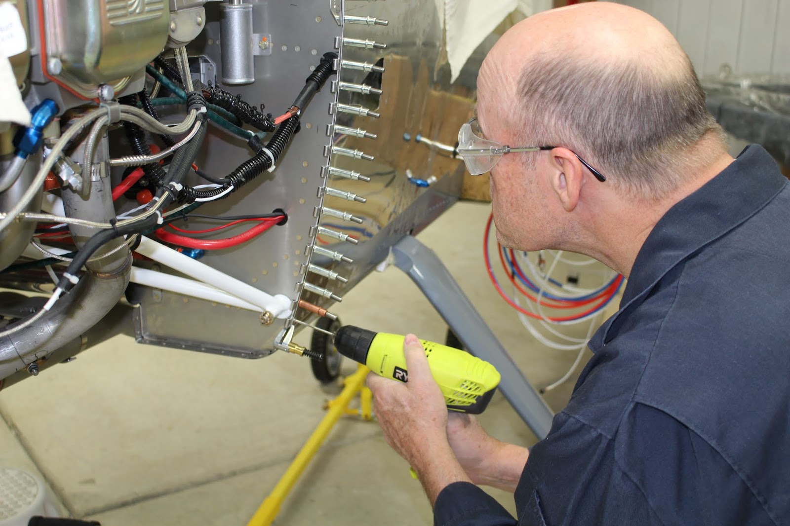
There were five holes along the vertical firewall hinges that would require blind rivets due to obstructions (lower engine mount bosses and the wiring harness); fortunately I had extra Cherry Max rivets in stock. Those holes were reamed out to #30 and skins re-dimpled with close quarter dies; the holes in the hinges were carefully machine countersunk by hand. All hinge parts were deburred prepped for paint, relabeled and painted. The Skybolt flanges were removed from the bottom cowl and all rivet holes were machine countersunk by hand with a fiberglass countersink bit. Each countersink was slightly oversize; this would allow the rivet heads to be covered with flox and smoothed during finishing. When the painted hinges were dry enough to handle, the firewall hinges were riveted to the fuselage. The cowl rivets required modified rivet sets that would nest into the deeper countersinks in order to squeeze the rivets properly. I ordered a few more rivet sets from Cleaveland tool to replace the ones I would modify. The first attempt was done on a rivet set that already had a flat spot ground into one side for tight clearances. Since I didn't have a lathe, I chucked up the set in my hand drill and carefully spun it against the side of my grinder which spun in the opposite direction. This worked, sort of... but the flat spot made it impossible for me to make a truly round taper. I squeezed two rivets with it, and they were less than ideal; the set was just a bit overground and it allowed the outer edges of the rivets to flare up and out slightly when squeezed. I tried to make a squeezing shim out of mild steel stock, but again, without a lathe this was an exercise in futility. I finally used a shorter stock rivet set and modified it in a similar fashion with much better results. With this improved tool I was able to rivet the remaining hinges to the bottom cowl successfully. The bottom cowl was installed on the fuselage, the hinge pins lubricated and inserted and the Skybolt flange rows clecoed back along the top edge. The top cowl was set in place and it was obvious that the flanges would require a bit of shaping before the cowl would fit properly, but the bottom cowl was looking good.


Time to take care of some minor details. I prepped and painted the firewall shims. The bottom edge of the baggage door was bent inward slightly to properly fit along the fuselage skin. I also filed the forward edge of the baggage door skin to fit better; a bit more will be required prior to painting, but this was sufficient for now. The door was placed back onto the fuselage and taped in place; the upper right edge of the firewall (including the forward top skin, forward baggage door support and firewall flanges) were taped in position against the forward edge of the baggage door skin to hold the correct alignment prior to riveting the flanges in place.


It was time to think about completing the baggage door installation. I had been dreading this for a long time because I knew how difficult it would be. With the forward top skin riveted in place, trying to get to the aft latch block screw holes on the aft side of the baggage bulkhead would be a nightmare. Up to this point, the baggage door inner skin was only clecoed in place; the instructions call for the baggage door to be fit carefully to the fuselage and taped in place prior to pulling a handful of blind rivets from inside the cockpit, securing the inner skin and locking the baggage door into the correct shape. The baggage door could then be removed to pull the remaining blind rivets. And before I could do any of that, I had to find ways to get in and out of the front footwell without dying. I started out by building a carpeted work platform that would fit inside the footwell and line up with the seat work platform built previously.. The pilot's control stick was partially disconnected and moved aside. Then I built a guard block that would fit over the seat belt center anchor tabs; it would be cushioned with a pillow. My first attempt at getting into the footwell revealed that it was too tight a squeeze. I had built the platform with a 2x4 support on the front edge so the backboard would clear the control column brackets. I could get into position - just barely - but it was impossible to get my arms into position to work. The platform was modified by removing the 2x4 and replacing it with a thinner board; a hole was cut in the backboard to provide clearance for the control column brackets. The second time I got into the footwell I could get one arm into the workspace, but it became evident that the only way I could get both arms into position is to go in arms-first... and if I did that, I was pretty sure I would not be able to get back out. (I've since heard a horror story from another builder who got himself into that position, without a backboard and with those seat belt tabs digging into his back. He was trapped for hours, but did manage to get out... with a lot of pain.) I was able to wedge the fuselage side of the door hinge up into position for match drilling, so I got out of there, made sure my hinge gap clearances were correct and match-drilled the hinge to the fuselage holes, clecoing as I went. The baggage door hinge pin was removed and I brought the door over to the C-frame table for riveting. Earlier I had checked my blind rivet inventory and discovered that I was almost out of the LP4-3 rivets called for in the plans, which is a round head rivet. When I took out a cleco I realized to my relief that I had dimpled most of the skin holes so they would take CS4-4 flush head rivets, and I had plenty of those. I set the first four in the center of the door and placed the door back on the fuselage to make sure it hadn't shape-shifted. I repeated this process several times until the inner door skin riveting was complete. Another test fit with the hinge pin in place revealed that a tab of excess hinge length was catching on the baggage door support strips. The door was masked and the offending tabs carefully cut off by hand and smoothed. The hinge pin, contrary to the plans, will be inserted from the front rearward; I suspect that with the windscreen bonded in place clearance from the rear will be limited. Satisfied with the door fit, I removed the fuselage side hinge for prepping and painting. When dry, it was riveted in place on the fuselage. The door was replaced, the hinge pin inserted and the baggage door fit well. Some method of holding the door open securely will need to be devised; more on that later.


Now to tackle the latch blocks. They had to be orientated correctly and labeled prior to drilling the mounting screw holes. Good access made the forward one easy, although it was still tricky getting the block to stay in place while the door was shut and latched. I used double-sided scotch tape to help secure it, and it worked pretty well. Van's suggested match-drilling the pilot holes very slightly to assure good placement, then finishing the pilot holes on a drill press before match-drilling again to upsize the holes. The block shifted slightly as the latch was engaged; one of the pilot hole marks was slightly off center, but not enough to cause concern. It was more important to be sure that the holes were drilled straight and that the block would be in the correct position to keep the door tightly closed when latched. After drilling the pilot holes, the forward block was held in place with #30 clecos while I worked on the aft block. I got into the footwell to see if I could reach the pilot holes in the baggage bulkhead from underneath, but that turned out to be impossible because of the wiring in place and the forward offset of the bulkhead skin from the fuselage brace. I had to remove the Garmin EFIS screen, detaching the GSU 25 module and connectors and carefully pulling wiring bundles out of the way with string before the pilot holes could be accessed. Since there was no guaranteed that I would be able to see the layout lines on the aft block, I transferred centering lines to the forward side of the baggage bulkhead. It was also tricky trying to get the aft block positioned in a good place for the latch pin to engage. The latch pin holes in each block were countersunk to aid in pin engagement, but it was still a struggle. The blocks are made of Delrin plastic that has superior low-friction, low-wear characteristics, but when holes are drilled through it the plastic tends to rebound slightly. Countersinking Delrin is also tricky because the countersink bit initially wants to slip on the material, but when it bites, it bites hard and it's easy to overdo it. The latch pin holes in the blocks are drilled by the factory, but they still wanted to grip the latch pins tightly and I had to ream the holes numerous times to get the pins to move in the blocks. This feel is exaggerated during engagement because the latch pins don't engage in a true linear fashion; the key mechanism causes the pins to shift slightly as the key is turned. I had to make sure pin engagement was assured before drilling the pilot holes. At times the engagement required such force that I was worried about breaking off the key in the lock, but after a lot of massaging I got the lock mechanism to work with the blocks well enough. It took a lot of tries to get the aft block taped onto the baggage bulkhead in the right spot for engagement, extrapolating layout marks to areas where they could be seen with the block in place. Eventually the aft block was placed, the baggage door was shut tight and the lock was engaged. I wasn't able to get any kind of drill behind the panel (or even spin a bit by hand) to match drill the pilot holes, but with some difficulty I was able to mark the pilot hole locations on the back side of the aft latch block with a sharpie. When the baggage door was opened and the back of the block examined, the layout marks looked pretty good. I crossed my fingers and carefully drilled the #30 pilot holes with the drill press. I used #30 drill bits, and also short sections of aluminum hinge pin stock, to hold the block in place on the baggage bulkhead and check the alignment of the bulkhead holes, block holes and baggage door latch pin holes. It was a great relief to find that my methods worked well; now both blocks were where they needed to be. The mounting screw holes were final drilled to #19; to accommodate the flat head screws, the inward sides of the screw holes were countersunk. Since I didn't have a helper to assist with cinching down the aft block, I used a socket on a swivel handle and taped the socket/handle in place on each lock nut in a position that would prevent the handle from rotating. Then each aft screw was tightened from the baggage compartment side with a screwdriver until tight, then torque sealed each lock nut. The forward latch block was retained with temporary jam nuts for testing the assembly. The lock nuts interfered with squeezing a few of the Skybolt flange rivets, so the block would be removed prior to riveting. The wiring bundles were released and relaxed; the Garmin EFIS screen was reconnected and reinstalled. I was really glad to get that job done.


I reapplied PVC tape to the right side of the forward top skin to pull the firewall back into alignment with the baggage door skin. The Skybolt flanges for the firewall were deburred, prepped, glued with Pro Seal and clecoed back into place on the firewall flange. I glued the flanges together as right and left halves to make prepping, painting and refitting easier. This method worked well for the horizontal rows along the bottom cowl, but not so much for the firewall rows. Some of the Pro Seal joints didn't hold up, and that made prepping for paint a bit trickier. A few clecos were inserted in strategic spots and masked to hold the rows together during painting. At one point one row separated after painting and hit the floor; fortunately the paint was barely marked. I had originally planned to apply a layer of Pro Seal between the flanges and firewall tabs, but it just seemed to be too messy and risky, so the Skybolt flange rows were clecoed to the firewall flanges, alignment was confirmed and the flanges were riveted to the firewall. Then the forward latch block was reinstalled with washers and lock nuts, torqued and sealed.


I recalled reading somewhere in the instructions that Van's recommended applying Pro Seal between the stainless steel firewall tabs and the fuselage skins. I had assumed that this was reduce infiltration of engine compartment fumes and carbon monoxide into the cockpit. I had planned to do so, but then decided to run a bead of RTV around the perimeter of the flanges after all riveting was completed. Soon after riveting it occurred to me that perhaps the Pro Seal application was suggested to prevent dissimilar metals electrolysis and corrosion between the stainless steel and the aluminum. I had previously dismissed this thought (stainless steel is corrosion resistant, right?) but builder paranoia being what it is, I decided to do some research. Sure enough, electrolysis corrosion between stainless steel and aluminum was a distinct possibility. I immediately began fretting at full steam. Why oh why didn't I do it right the first time? If I didn't immediately drill out all those set rivets, mangling hinges and flanges in the process, the firewall tabs would rot away within a week and the front of the airplane would disintegrate when the engine was started. And of course all of this occurred to me on a Saturday morning, so I had to endure two nauseated and sleepless nights before calling Van's Builder Support on Monday and confessing my sins. The tech was forgiving, and allayed my fears. Yes, there was a potential for electrolysis and corrosion, but not on a scale anywhere near what I had feared. Sealing the joints with RTV would indeed help to protect them, and unless the aircraft was heavily exposed to salt water it would be unlikely that I'd see any corrosion in what remains of my lifetime. That was a relief to hear.
The finishing touch on the baggage door was applying the strip of closed cell foam underneath the hinge to reduce any rainwater intrusion into the baggage area. I'll have to take further steps to protect the engine management electronics that are housed in the lower well, and I already have some ideas about that. The other thing I'll need to address is how I intend to hold the baggage door in an open position. I don't want to just swing it all the way open; that applies far too much stress on the hinge and skins. I've seen a lot of good ideas implemented by other builders, and I've come up with a few of my own. Rather that build in support arm attached to one side or the other, I'm thinking about a collapsible two-sided aluminum support with machined pins that would fit into the door latch pins and snap bushings on either side of the door and be secured to the longeron or bulkheads. My final work on the airplane in 2019 was to design those machined pins.


Well, that's it for this year. A lot has happened, and I'm recently reminded of it in detail because yesterday Steve Thorne (Flight Chops) put out a call for his friends and fans to submit video of what we did in aviation this year and he'd share them with us all on New Years Day. Of course that lit my creative fire, and about five hours later I had a 3:42 video of photos and clips highlighting all the amazing aviation adventures I've had this year. A formation flight with the CH2A in January; a Cirrus SR22 familiarization flight with Mike Hull in May; my date with the CAF B-29 Fifi and my whirlwind trip to AirVenture in the Yankee Air Museum C-47 Hairless Joe in July; Flight Chops Day at CH2A in October; checkout in a Diamond Star DA40 in November and subsequent flights around Detroit and to Roscommon; more training in the CH2A Chipmunk in December; plus all the progress made on my RV-8 this year. There was so much more that I left out of that video; more flights; more sim work; the EAA Chapter 113 Homebuilder's meeting at my shop; all the great Chapter 113 and 194 meetings and events; the Hammer Dance video and more. I will be posting the video I made for Steve on my YouTube channel, but I want to wait until after he releases his video. Check my YouTube channel (goatflieg) and watch for Martin's 2019 Aviation Adventures, as well as dedicated videos for many of the events mentioned.
There's more, of course... there's always more. Great trips; great times; great photos... and to top it all off, I became a grandfather this month. Yep... quite a year... but just wait. Next year will blow your mind. Stay tuned... and I'll see you then!