Last year ended with masking and a bit of painting before bolting the canopy rails to the cockpit rails and the slide to the fuselage. Temporarily fitting the canopy frame indicated that the fit was mostly good, although the aft locking pin tends to bind up when pulled tight into the block. This might change when the height of the forward hoop in the rollers is set by the fit of the plexiglass. That stage of fabrication will wait until warmer weather this summer.


The first complete fitting of the baggage shelf and aft bulkhead was more difficult than I expected. Care must be taken not to allow any dropped screws to fall through a crevice and end up below the baggage and cockpit floor panels. Trying to retrieve them from underneath the riveted flooring is a nightmare. Practice made the fitting process somewhat easier, and treating all cockpit screws with Boelube and careful tightening assured no stripped screws, heads or nut plates.


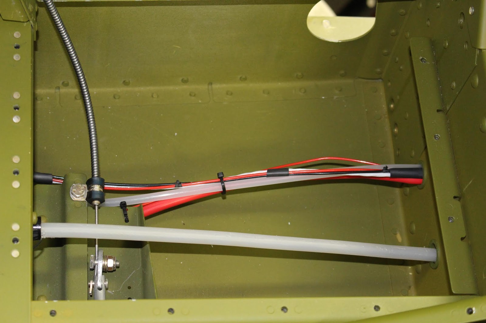
There were only a few more wiring details to address in the aft fuselage. The wiring from the flap position sensor needed to have the connectors installed and the flap motor and sensor wires routed through the bulkhead, under the flooring and through the spar box. The static air tubing needed to be routed through the spar box as well, and consideration was given for the future routing of the pitot tubing and all wing wiring. Trying to determine the best routing for all this remains a conundrum. It's likely that routing through the gear towers is the way to go, but actually doing that will probably be very difficult.


I did a little more fiddling with cockpit details, mainly for fun. I began to work out the assembly of the canopy latch and installed much of the cockpit flooring and side panels so that I could temporarily refit the seats. This was the first time the panels were screwed down snugly, and it went fairly well.


It was time for another big step: hanging the engine. The fuselage and engine table were both repositioned to optimal locations in the shop. I gathered the engine mount hardware and fabricated a long drift pin that would be used to help align the mounts. I went over the assembly procedure in detail and practiced the required steps to thoroughly familiarize myself with the process. Tail counterweights were affixed to horizontal stabilizer spar mounts to make sure the fuselage would not nose over with the added weight of the engine. I set up the engine hoist and practiced lifting the engine out of the nesting foam. Then I enlisted the help of Harry Manvel and we got the engine mounted to the fuselage. Many builders are aware of how difficult this process can be due to the geometry of the Dynafocal engine mount; the holes don't actually line up until all bolts are inserted and tightened. Usually the top bolts are easier than the bottom bolts, and the last bolt is the most difficult to get inserted. In our case, the top bolts turned out to be quite difficult; the third bolt wasn't too bad, but the fourth bolt took some doing. Harry and I spent two hours each getting the first three in; I spent another two hours getting the last bolt in and getting all bolts torqued. I had to fabricate more drift pins of varying lengths and tried repeatedly to displace them with the bolts before I was successful. Even getting the cotter pins installed through the bolts and castle nuts was tricky. The pins had to be partially inserted, then the bolts clocked to a certain position to allow the pins to be fully inserted. Then the bolts were re-clocked so that the closed end of the pin was shrouded by the cast receptacle of the crankcase and the open ends faced outward so they could be bent and secured. Once the installation was complete, I checked the weight of the tailwheel with a scale so that I knew the balance of the fuselage with the counterweights installed; just over 60 lbs. indicated. Not all that much, but enough to stay safe if I was careful. The added weight of the engine required the main gear tires to be brought back up to the correct pressure. Once that was done I was able to reposition the fuselage in the shop to improve access for the firewall forward work to come. The entire process took seven man-hours from start to finish, and it's quite inspiring to have the engine on the fuselage.


The first accessory to be installed was the Vetterman 4-pipe exhaust, which is recommended for Superior IO-360 engines with horizontal cold air induction. The stainless steel pipes are built with precision and fit well, but some additional fabrication is required for the support brackets and the required aluminum and steel strap stock is supplied by the builder. I also had to get different hose clamps for securing the brackets to the pipes; the clamps supplied by Vetterman were too small. Installation of the support hardware tends to be customized by each individual builder; Vetterman gives guidelines, but it took some experimentation before I was happy with the way the pipes were hung. I'm hoping I won't have to modify the setup for a better fit with the cowling; we'll see. The heat muff is assembled around the 1-3 pipes. It's a tight and fiddly fit, and the sheet metal screws supplied by Vetterman weren't up to the task. I replaced them with larger stainless steel screws.


I bolted the fuel injection servo onto the intake manifold, using the engine build photos as a guide. That proved to be a mistake; more on that later. I also figured out the alternator installation and order of assembly. I mounted the alternator bracket, safety-wired the bolts and hung the alternator. The alternator drive belt has to be put in place around the nose of the engine before the starter flywheel is placed on the crankshaft. Then the belt can be threaded into place. I will set the belt tension and safety wire the adjustment bolt after the prop is installed.


At this point I thought I should finally open up the prop crate and inventory the parts for the prop, governor and spinner. I did some homework on the prop installation process for future reference and prepared to install the prop governor on the rear accessory case. It took a lot of investigation for me to figure out the orientation of the governor and gasket on the mounting pad. Nothing seemed right, and the governor gear didn't want to fit into the engine drive socket. Calls to Barrett Precision Engines, Whirl Wind and Superior didn't provide any answers that worked. I ended up texting Allan Barrett for the answer. As a side note, Allan has retired from BPE to do battle with lung cancer and I had been in touch with him a few times to share some encouraging words and progress updates. I didn't want to treat him like an on-call A and P mechanic, but I was stumped and he was the only one available to help at the time. I sent him photos; he sent replies and we got it figured out.


Figuring out the cable bracketry and installation for the prop, mixture and throttle was another convoluted process. I sorted through the hardware and determined what was supposed to go where, and in the process I discovered a missing engine case bolt. Allen must have removed it when he installed the data plate and never replaced it. I needed to get longer case bolts for the mixture cable brackets anyway, so it was no problem... but I was quite surprised the missing bolt wasn't noticed by any of us during the build.


The fuel injection servo can be oriented any one of four ways, depending on the application. When Barrett got the engine ready for the test stand, they mounted in a way that worked for their dyno linkages. I used the photos I took during assembly as a reference when I bolted the servo on to the intake manifold, but researching installation photos taken by Van's as well as other RV-8 builders revealed that I had to rotate the servo 180 degrees to align the mixture and throttle actuation arms with the corresponding Van's brackets, which were designed for Lycoming engines. Since my engine was a Superior IO-360 with horizontal cold air induction, much of the bracketry would have to be either heavily modified or replaced. More research would be required; in the meantime I turned my attention back to the prop governor.

The Van's bracket for the prop governor cable is held onto the governor by three of the six governor cover screws, and has to be modified slightly to fit on the Jihostroj governor supplied by Whirl Wind. The outer two bracket holes have to be slightly elongated to allow the case screws to align with the threaded case holes. The cover screws come from the factory safety-wired in place and unlike other governors, there is no external evidence that the clocking of the actuator arm can be adjusted. The way it's designed, the arm has to stay as delivered from the factory for proper travel. It appeared to me that the only option I had was deciding which three screws to use to get the right bracket alignment. I took a best guess, cut the safety wire and removed the screws. I carefully modified the bracket mounting holes by hand until I had satisfactory alignment, then mounted it on the governor, torquing the screws down and rewiring the safety wire. Since I had very little practice with safety wire prior to this, it took a few tries to get it right. When I reinstalled the governor on the engine, it looked like that bracket location might not work for the correct cable travel. I removed it from the engine, cut all the safety wires off, removed the bracket and checked to see if any other orientation would work. No such luck... so back on it went, retorqued and rewired... just another waste of time.


The alignment still wouldn't work; the cable rod end bearing would hit the stop boss for the actuator arm, preventing full travel. I double checked the instructions supplied by Whirl Wind; no mention of any possibility of re-clocking the back cover. The fact that the cover is safety wired by the factory tended to reinforce that assumption, so I began to think about ways I could make the current set up work properly. I worked for a couple days designing an adapter for the actuator arm that would allow adequate clearance while keeping the correct travel geometry. Lacking proper machining tools, I had to hand carve several prototypes out of aluminum strap stock, refining the design as I went to try and obtain the desired result. Each one was close... but not good enough.


After another sleepless night, I realized that despite all evidence to the contrary there must be a way to re-clock that back case to optimize the travel of the actuator arm. I reexamined photos from other builders using the Jihostroj governor and realized that their case alignment was indeed slightly different from my own. Examining the unit more closely revealed the possibility that loosening all six screws would allow the inner part of the back cover to be rotated within the outer collar to the ideal position and tightening the screws would cinch it back down. Checking with other builders on the VAF website confirmed my suspicions, so I cut the safety wires again, loosened the screws, re-clocked the inner cover, tightened the screws and rewired them... shedding the usual amount of blood from being repeatedly stabbed by that infernal safety wire. The governor was remounted on the accessory case, the cable was attached and the travel was dialed in to the optimal range. Completely full travel wasn't quite possible, but according to Van's this is a normal condition. Full coarse pitch travel of the actuator arm is almost never used; as long a full fine pitch can be achieved, the adjustment is operationally correct. Once dialed in, everything was torqued and sealed. I did mention to Whirl Wind that they might want to modify their instruction manual and mention the option of re-clocking the back case of the governor. That would certainly save novice builders such as myself a lot of needless work and worry.


One control down; two to go. Van's mixture bracket base would need to be modified to fit the Superior crankcase, and a new bracket setup would be required for the throttle cable. I began to design my own throttle bracket, but some more research revealed that Showplanes makes a bracket set that will mount on the Superior cold air intake manifold; it will work with various throttle and mixture cable setups. I ordered a set for my throttle setup and got to work on modifying the mixture bracket base. Once again my lack of machine tooling meant that some hand carving was required. With a lot of effort, I got close... but I realized that I would be removing so much material from the bracket that reinforcement plates would have to be welded onto the bracket, as other builders have done. Since I had to farm out the welding, I might as well farm out the rest of the machining. One of my PTK buddies referred me to St. Pierre Inc., a local machine shop that quickly became another valuable resource for me. They got the mods done quickly and properly. More test fitting with other bracket components revealed that a little more whittling was required for proper operation. Once I was satisfied with the lever travel, it was removed for hi-temp coating before final installation.


St. Pierre also modified an oil fitting for me; the restrictor fitting supplied by Van's was an angle fitting that proved very difficult to install and clock properly. St. Pierre modified a straight fitting with a brass insert to make it a restrictor fitting that was much easier to install and connect.


When I ordered the Showplanes bracket I spoke to them about my application to make sure it would work. Their bracket is ideally suited for cables with different retaining collars than the Van's cables; they warned that I might have clearance issues using the cable mounting angle bracket they stock for the Van's-style cables. The first test fitting revealed this to be true; the bracket needed to be bent slightly downward to provide the clearance I would need. I took some measurements to determine the amount of deflection required and the optimal place to bend the bracket. Since I didn't want to compromise the strength of the bracket, I wanted the bend to be done precisely. I paid a visit to my friend Leo Knowlden's home shop; he had a sheet metal brake and we got the job done correctly. The cable mounting angle bracket had to be bent slightly to offset the change in geometry created by the bend in the Showplanes bracket, and another hole needed to be drilled in the Showplanes bracket to orient the angle bracket in the right direction so that the throttle cable was pointing toward the throttle actuation arm. When more test fitting indicated the setup would work, the parts were removed for hi-temp coating prior to final assembly.


Another minor annoyance was getting additional bolts for the bracket installation. Van's supplies two mounting bolts with the heads drilled for safety-wiring. The Showplanes bracket and Superior manifold require four bolts, so I ordered four new bolts with drilled heads from Aircraft Spruce. For test fitting I used some undrilled bolts purchased at the local Ace Hardware and seen in the photos above. When the Aircraft Spruce bolts arrived I realized that I had accidentally ordered fine thread bolts, instead of the coarse thread bolts required. D'OH! I thought about it... I could try to drill holes in the Ace bolt heads; probably break a few bits and end up with botched holes. I could have St. Pierre drill the heads... and spend $20 on $2 bolts. Or I could order two more bolts from Van's... and have to wait for them to show up. Oh well; the parts were at Flow Coatings, anyway... I had time, so the order was placed. I also ordered a different mixture arm from Airflow Performance to get clearance for the cable rod end hardware. By the way, you'll notice in this photo that one bolt has been shortened slightly; that was required because of the tight fit between the bracket and the #1 exhaust pipe. Just another day in novice homebuilder Paradise.

While waiting for coatings and deliveries I kept busy on other tasks, working on the oil and fuel connections and beginning to install various engine sensors. Working on installing the manifold pressure, oil pressure and fuel pressure sensors in the sensor block got confusing because the plans show different setups on different pages, depending on the aircraft model and engine model. More than once I found myself reading from the wrong page and having to rearrange things. When the brackets came back from Flow Coatings I got to work installing the mixture and throttle cables. The mixture bracketry with its bellcrank and odd angles took some fiddling and the throttle cable access was tight, but both cables were installed and dialed in. When the correct bracket bolts arrived from Van's I got them safety-wired... and shed more blood in the process. I'm starting to really dislike safety wire.


Proceeding with sensor installation, I got the CHT probes and the oil pressure sensor in place. For my tach readings I'm using a Hall Effect sensor installed in the right mag. Since the mag is already in place and timed, getting the sensor screwed into the inner side of the mag surrounded by obstacles was tricky, but I got it done. I called Jason at Aerotronics with a few wiring questions; he answered them and sent along some small ring connectors. Installing the EGT probes was next, and it felt kind of scary drilling holes into brand new stainless steel exhaust headers, but it went well.


The oil and fuel pressure sensor connections were fairly straightforward, but plumbing the manifold pressure sensor required some additional ingenuity. The Van's firewall forward kit included plumbing that would route the manifold pressure through the firewall to connect with components in the panel. I elected to use the top part of the sensor block as the location for the Garmin manifold pressure sensor, but the hose supplied by Van's wouldn't reach that far. I decided to fabricated a solid line that would run from the sensor block across the firewall to an optimal location for connecting to the Van's hose, which connected to the #3 cylinder head. Garmin recommended the use of a snubber fitting that acted in a similar way to a restrictor fitting for the manifold sensor, but didn't indicate where it should be installed. Jason at Aerotronics suggested placing it between the sensor and the block.


Barrett supplied an oil hose that connects the prop governor to the fitting in the nose of the crankcase for the prop oil supply. Figuring out the best way to route the hose required some more investigation. I pondered fabricating a solid line similar to a typical Lycoming setup, but the hose from Barrett looked like a quality piece, so I fabricated a tab that would allow me to secure the hose to the side of the crankcase with an Adel clamp. This would also become a convenient way to route some wiring, but the hose created other issues with the front baffles. More on that later.


With all sensors in place, it was time to start wiring them to the Aerotronics harnesses that I had already routed through the firewall. Like much of the firewall forward construction, this would all be custom work. There was no blueprint or instructions on this; only general guidelines, so my approach was tentative. I sorted out the wires, figured out where they needed to go, and then thought long and hard about how I wanted to route and connect them before doing any cutting or splicing. The Aerotronics wires were all labeled, but the labels were placed at the end of each wire. I had to add labels to each wire at the firewall, and when the wires were later cut to length they would be labeled at the new ends. I tried to plan ahead and make sure that I wouldn't create an installation that would become a problem later on. There were lots of considerations to keep in mind, such as proximity to heat sources, potential vibration sources, any flexing motion of the engine in the mount in normal operation and making sure there all these operating parameters would not cause any strain on wires or connectors. I also had to educate myself on all installation guidelines provided by Garmin, Aerotronics and other component manufacturers. All of this had do be done right; my life will literally depend on it. Like much of the firewall forward work, it was done in many small stages; I am always doing a little of this and a little of that, switching between plumbing, assembling, wiring and fitting various components. I've described it all as "cautiously creeping into the firewall forward forest". There were a lot of runs to the local hardware/auto parts stores and a lot of small orders from Aircraft Spruce. Quite often, I didn't know what I needed until I needed it; then I had to get it.


I brought all the baffle components into the shop, sorted them, removed the plastic coatings and relabeled them. I began reading the instructions and reviewing the prints, trying to figure out what needed to be done and when it should be done in relation to other firewall forward tasks. There were a lot of little details that were tended to, such as ordering a cap for the unused tach drive, installing it and figuring out the best way to safety-wire it. The bosses on the unused vacuum pump pad became a convenient solution to various issues like safety wiring, securing other wires with Adel clamps and a good place to bolt the ground strap from the engine to the firewall.


Another issue was the fuel line that connects the fuel injection servo to the distribution manifold, or spider. Barrett did not supply a hose or line for this, because it's another part that has to be customized by the builder. I had also forgotten about the fuel flow sensor, or red cube, and had to do research on where along the line it was connected. I got a lot of different suggestions from VAF and the websites of other builders. I chose to install it just above the fuel injection servo, between the servo and the spider. I had to order fuel hose and fittings and fabricate two hoses; one for the servo/red cube and one for the red cube/spider. I knew the fitting sizes on the servo and spider and I knew what fittings I'd need for the red cube, but had no clue which fuel hose to get. I guessed, and placed another order from Aircraft Spruce... along with tooling for hose assembly and banding firesleeve, etc. When I received the parts, I realized my guess was wrong; the fittings didn't work with the hose. Aircraft Spruce also made the rare misstep of sending an incorrect fitting in a bag labeled with the correct part number; a tee instead of a nipple. I could order new fittings to work with the hose which were very expensive, or order different hose to go with the fittings I had. I chose the latter and ordered more hose, and Aircraft Spruce also sent along the correct fitting with their apology. Just as an experiment I fabricated the short servo/red cube connection as an aluminum fuel line that would probably work, but the red cube manufacturers recommended using hose on both sides for protection against vibration. At least it got me started on setting my dimensions for hose lengths.


While I waited on the new fuel hose, I started work on the baffles. The initial fabrication was a fun change back into familiar territory... at first. It didn't take long before I realized that although each cylinder baffle was cut to the shape required to fit around the valve covers, the shape cut was only an approximation. Each baffle would have to be relieved along those curves in order to get enough clearance for the baffle mounting screw holes to line up with the bosses on the cylinders. Another common issue with Van's baffles concerns cracks and breaks that can develop along the #4 cylinder and left aft baffles where the oil cooler is mounted. There are known fixes for this that I would incorporate into the initial fabrication so that I wouldn't have problems later. I fabricated a reinforcement plate for the #4 cylinder baffle, ordered some aluminum angle stock and fabricated a reinforcement angle for the area where the two baffles are riveted together.


When the new hose arrived I worked on fabricating the red cube hoses. It took a few tries to get this right; there was a learning curve on fitting assembly and extrapolating measurements to get the correct length. Eventually I ended up with two satisfactory hoses. Unfortunately the red cube/spider hose encased with firesleeve would not fit through the rubber grommet that Barrett installed in the right bottom baffle hole. I removed the grommet and added numerous layers of heat-shrink tubing over the firesleeve for abrasion protection, but it may not be enough. I've been advised to make a custom grommet that will fill up the small space around the hose and further protect it from the metal edges of the baffle hole. Incidentally, all fuel and oil hoses were cleaned thoroughly with gun cotton and compressed air before final installation.


Back to baffles. Fabrication continued, solving various puzzles along the way. I'll just hit the highlights on the baffle construction because it's turning out to be a long convoluted process; if you want a detailed chronology, refer to my KitLog Pro site. The left aft corner parts were complicated by the additional fabrication of the braces and the number of parts coming together. The diagonal brace that attaches to the cylinder head and helps support the left aft baffle and oil cooler had to be fabricated in several stages after test fitting, and I ended up making a second one to improve the fit. I don't want to paint the baffles but I do want to prevent corrosion where parts come together, so any non-alclad or sandwiched parts are getting painted with blue hi-temp paint, which has to be heat-cured in the toaster oven I borrowed from the kitchen. For other items I'm putting hi-temp RTV between the parts. There are a few areas where I may attempt to bond the parts, but I need to do some research first; more on that later.


Cutting out the rectangle in the left aft baffle to allow air through the oil cooler had me slightly concerned but it was easier than I thought and turned out well. The same can be said for the hole that allows air into the heat muff; proper jigging and the right hole saw made it easy.


Cutting the overlapping holes for the ignition wire clamps was actually fun and I was very happy with the result, although later on I needed to modify one end of each opening into a hex shape to allow the spark plug terminals to fit through.


I learned some lessons on refining the baffle shape after getting the first one done. After that, I made a paper template of the shape of an untouched cylinder baffle and used it to draw a matching shape just above the existing cutout. That made the remaining three modifications go smoother, although it was still a pain.


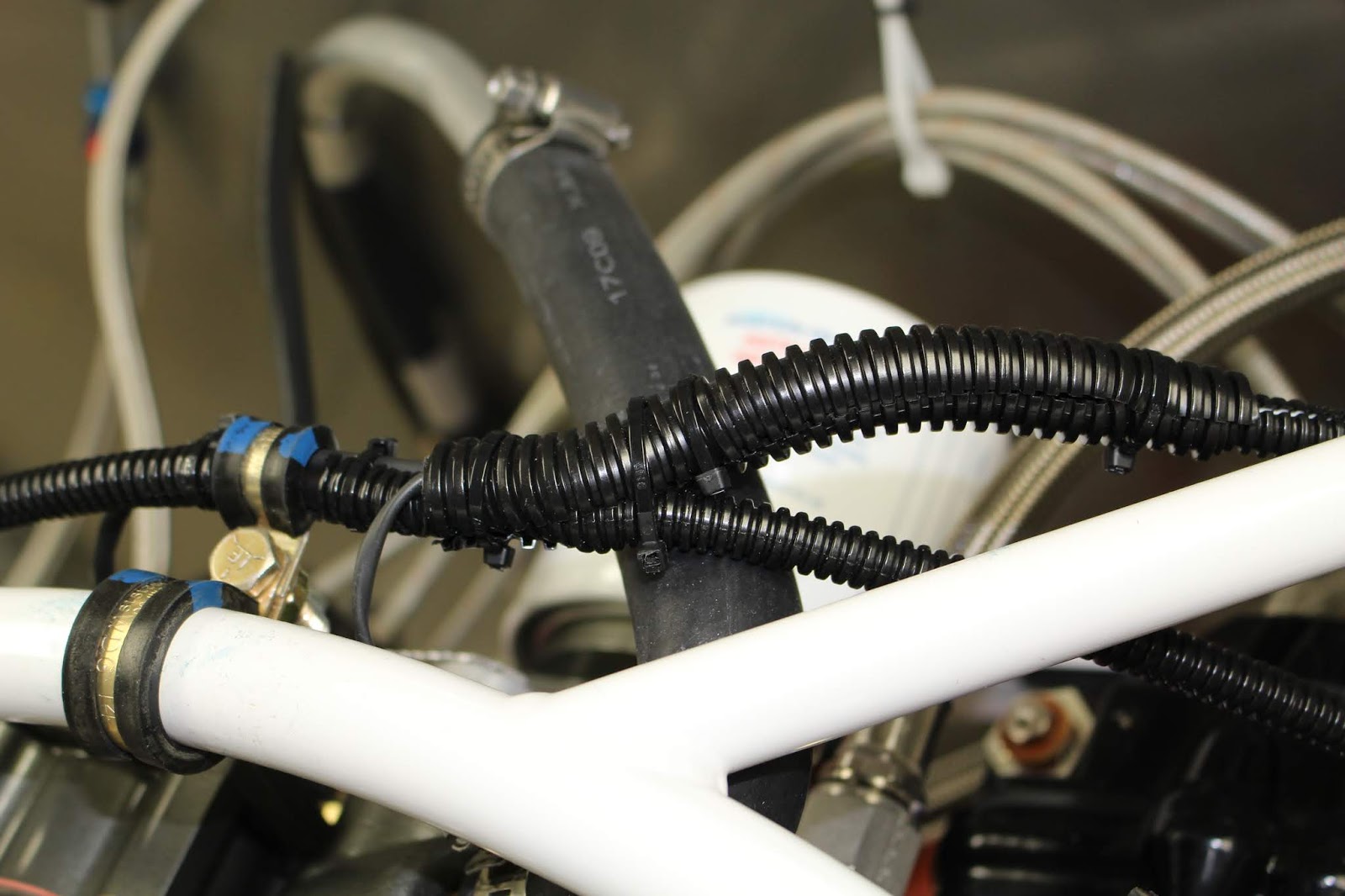
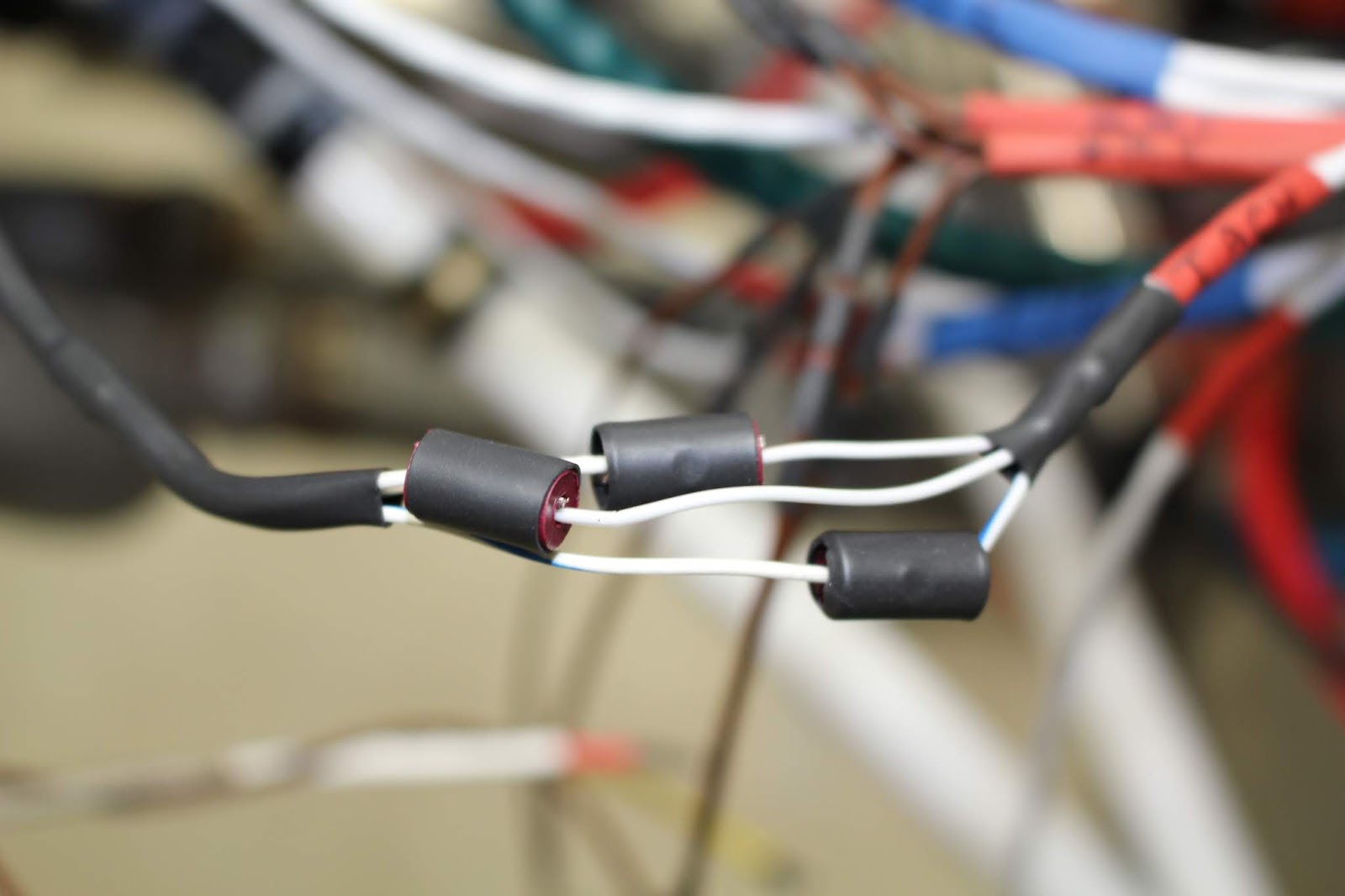
When I'd get burned out on baffles, I'd switch to wiring sensors and made gradual progress on each front. Lots of routing, labeling, bundling, wrapping with heat shrink tubing, clamping and securing going on. The red cube came with OLC-1 connectors; I asked Jason at Aerotronics and other builders about them and although expensive, they were highly recommended so I made the investment and bought 50 more from Aircraft Spruce. Most connections that would have been made with ring connectors will now be made with OLC-1 connectors. Another trick I utilized when securing wiring runs was the zip-tie-hose-spacer trick I learned from Synergy Air, which can be seen in some photos. It's a good safe way to stabilize wires without risk of chafing. Another task addressed was installing the crankcase ventilation hose and pipe, which also received heat shrink tubing at potential firewall contact points.


When doing initial assembly on the right aft baffle, I made a fairly significant error; it was one of those classic mistakes of getting the inside and outside of a part mixed up. When I riveted the heater scat tube flange onto the baffle, I didn't double check my orientation and put it on the inside instead of the outside... with heavy round-head rivets and RTV sealant. I also neglected to put the mesh screen in between the parts. The parts were pretty deformed by the process and drilling out the large rivets would likely make them worse. I labeled the bad parts with a sharpie and made up a list of the parts that had to be replaced. Then I thought since I'd have to wait a couple days for them to arrive, there would be no harm in trying to disassemble the parts and see if I could save and reassemble them correctly. Fortunately it went very well; the parts were separated, cleaned off and carefully reshaped without further damage. I put the screen in place with RTV, riveted the parts back together and added a bead of RTV around the outer edge. When I was done, you couldn't tell that repairs had been made... unless you look closely and notice the shadow of the sharpie marks.


Test fitting the aft baffles to the engine was much trickier than anticipated because of the many obstacles on the engine and baffles that make it very difficult to get them into position. The right aft baffle took many tries just to figure out how to get it into position. I had to remove and invert one of the hose clamps from the cylinder oil feed line to get the clearance to get the inner cylinder baffle into the correct position. When I got it close, I realized it also needed to be custom-fit to the crankcase, so it had to come off and go back on many times, carefully trimming away numerous areas until I was satisfied with the fit. Trying to get the holes lined up with their screw bosses was just as difficult as it was for the cylinder baffles, and there is one mounting screw that is awkwardly located behind the oil dipstick tube. Access is nearly impossible; I'm not sure how I'm going to get that screw in there. I've been told I'll have to remove the tube and reinstall it, but I hate having to remove components that were installed by Barrett... especially a component that needs safety wire. The left aft baffle is mounted with a bolt that goes through a spacer tube between the crankcase and the baffle; another spot that's impossible to reach with fingers. I came up with a zip tie tool that allows me to hold the spacer in position to slide the bolt through. Both aft baffles were temporarily installed and with the side and aft brackets clecoed together, I could temporarily mount the oil cooler and determine how to clock the elbows to optimize the oil cooler hose paths. The prints indicated that part of the aft mounting flange of the oil cooler would need to be relieved for hose clearance, but that appeared to be unnecessary for my installation. I was able to finish fabrication of the custom angled brace and test the fit; a few more minor tweaks may be needed but it should work well enough. The aft baffles overlap at the top center, behind the top aft mounting bracket. The overlapping baffles were then clamped together to the top aft bracket so that screw holes could be match-drilled through the bracket holes and through the baffles. I took precautions to prevent chips from getting into engine crevices and the process went smoothly. Now I fully understand how the aft baffles are fitted, but I still have trouble imagining how to get them into place with the cylinder baffles and other parts riveted to them. That's ok... they still need a lot more trimming and fitting before I have to worry about that.


I faced the next big baffling challenge when I started working on the forward right baffle. I always wondered how the prop governor oil hose would be accommodated by the baffles. The Van's plans and instructions assume you're using a stock Lycoming engine with a stainless steel oil line connecting the aft-mounted prop governor to the fitting in the nose of the crankcase. They provide a pilot hole through multiple parts that are to be drilled out to 1" diameter and fitted with a rubber grommet that the oil line runs through. I investigated replacing the hose supplied by Barrett with a stainless steel line, but even the stock Lycoming lines cost about $350 and they probably wouldn't fit my Superior engine the same way. Fabricating a custom line out of stainless steel is much more difficult than an aluminum line, and an aluminum line should not be used in this application. Anyway, I had a perfectly good line already; I just had to figure out how to get it to pass through the baffle and support angle. The hole would have to be bigger and slightly oval to work. I started with the front lower mounting bracket screwed in place on the crankcase. Then I made paper templates to determine exactly where the oval hole should go. I had some flexibility in that the elbow fitting could be adjusted slightly to move the hose fore and aft if necessary. Once I had a rough idea of location I transferred the layout onto soft aluminum scrap and fabricated a test part. After more test fitting and making a second test part, I had something that might work. Now I had to see where that oval would end up on the actual parts. The answer was discouraging. The actual baffle would be relatively unaffected, but the mounting bracket would be severely compromised. I marked the parts with the hole location and did a lot of thinking.


The last photo above shows where the penetration should go. The baffle is upper right; the small circle around the rivet hole is where Van's wanted the 1" hole to be for a hard line; the oval is what my oil hose requires. Compromising one rivet hole is no big deal; I can work around that. But the support bracket on the left is almost completely bisected. I could see if I could have a custom support bracket fabricated with a longer flange along the forward inner edge that would give me enough reinforcement to keep the part viable. But trying to get a one-off part like this made up with the right bends in just the right places, while keeping the rivet holes correctly aligned in two planes, would be difficult at best. Or I could add my own doubler plate onto the bottom inside of the baffle that would reinforce the area using the stock parts without changing the spatial orientation of any of the stock parts. Or I could bite the bullet and have a custom stainless steel oil line made up. Every option brings its own pain, but a decision must be made. I just wasn't ready to make it yet.
As a palate cleanser, I asked my EAA Tech Counselor Dan Jones to stop by and give the airplane another inspection. Although I had made good progress into the firewall forward forest, I still had a lot of questions that I wanted to ask to make sure all the paths I'd laid out so far were truly viable. It took a while for our schedules to mesh, but he came by at the end of February and we discussed many issues that I wanted clarified, or at least commiserated. He approved of all my plumbing, control cable and wiring connections and routing decisions thus far and was very complimentary about my workmanship, which still amazes me. We discussed the final fitting of the baffles and cowling and the best way to proceed to have all the elements come together properly. Dan suggested making the custom grommet for the red cube-spider fuel line; that line has to be well stabilized in that location to optimize safety. He suggested I run a dedicated ground line from the engine-firewall ground strap to the avionics ground plate to optimize the grounding of the block. He mentioned that the crankcase vent tube should be positioned in such a way that it receives some positive pressure at the outlet. Otherwise, negative pressure could create a siphon effect that can quickly pull all the oil out of the engine. He thought that using my prop governor oil hose was the right thing to do, figuring out the best way to reinforce around the baffle parts with doublers and even bonding the parts together with an aluminum epoxy in addition to riveting to further stabilize the assembly. He spent over an hour here and if it weren't for our own time limits we probably would have talked another hour. It was a fun visit that was also very helpful and very encouraging.


Freshly motivated by Dan's visit, I jumped into more wiring work, routing and securing the ignition wires and finished connecting the EGT and CHT sensor wires. I went over all my wire bundles and got them as neat and secure as possible while making sure they were safe from any chafing and had adequate slack. I also got the Garmin shunt mounted onto the firewall, fabricated the alternator/shunt cable and got it routed and installed. I routed the shunt sensor wires over to the shunt but I want to refer to the Garmin manual before attaching them. I ordered four more feet of 6 gauge red battery cable to run from the shunt to the panel circuit breaker, along with lug nipples and other supplies. When they arrive and are connected, my firewall wiring should be complete... I think. We'll see. It certainly looks good to me right now.


Turning my attention back to the baffles, I committed to the plan of using my hose. I designed a doubler plate and fabricated it out of spare sheet, match drilling some rivet holes shared by the baffle and bracket and laying out others by hand. I carefully bent it into the right shape to nest into the baffle, drilled the additional rivet holes in the doubler, then match drilled the extra holes in the baffle before dimpling the extra holes in both parts for flush rivets. To prepare for the oval hose hole I refined the layout and jigged up the parts as well as possible before using a 7/8" hole saw to create the oval. It didn't go quite as smoothly as I had hoped, but with some massaging I'm pretty sure it will work. The oval pattern only partly overlapped the doubler plate, so the half-oval notch was carefully nibbled out, filed and smoothed to match the other parts. During the final assembly the mounting brackets, baffle and doubler plate will be bonded with aluminum epoxy before riveting.


That brings us up to date. I've improved my working schedule and reduced my distractions so I'm able to work on the airplane almost every day. I hope I can keep the momentum going, because this is the tough part of the journey. And when the going gets tough, the tough get tougher. Wait, that's not it... rougher?.... damaged?... loopy?... out?... what is it? Oh yeah... the tough get going. Speaking of which, I gotta go. Stay tuned.