Wow... almost three months to cover. This is gonna be a long one. There were lapses in building this fall for some travel, and I've been keeping my flying status current. I've made a lot of videos this year for my YouTube channel and captured a lot of sunsets and sunrises. But I'm back on a roll again and my momentum is gaining strength. I'm getting closer and reached some milestones. Let's dive in.
There was a two-week hiatus in August, during which I composed the previous blog post. When I resumed work, it continued on the canopy frame. I want to install an aft pull knob on the canopy, as other builders have done. My canopy will be a snug fit with the windscreen and forward fuselage and it will be easier to pull it open from the center of the aft end, rather than pulling from the latch handle. To that end, I drilled a hole in the aft tip of the canopy and frame for a long screw to pass through for the pull knob. I had previously drilled out the temporary rivets that had held the canopy to the frame and was able to remove the drilled-out tails from the inside the frame by dropping them out the larger screw hole. The hole ended up slightly off center of the frame tube with a forward bias; I knew the tube strength had been compromised and also wanted to have the screw head cinch down to a flat surface, so I fabricated a small reinforcement tab, sanded the powdercoating off the required area of the frame and had Leo Knowlden weld the tab onto the bottom side of the tube. I added some fillets of aluminized epoxy and sprayed the modified area satin black. It didn't match the powdercoating all that well, but it will protect the surfaces and will be hidden by the skirt.


Using some spare lumber, hardware and two sawhorses joined together, I built a canopy frame support that would allow me to work on assembling the canopy and skirt to the frame and do additional finish work on the skirt with the assembly off the fuselage. The frame would be swapped back and forth from the fuselage and the frame as needed for fitting. Other miscellaneous work would include filing and smoothing the edges of the forward baggage door to allow a better fit, and mounting a smaller fire extinguisher on the right console panel for easier access while in the cockpit. The airplane now has two fire extinguishers installed; the larger one mounted on the pilot's seat back and the smaller one on the right console.


Work continued on the canopy skirt. I could only tolerate it in small doses, so I would often do other jobs while epoxy was curing. Slits were cut in the forward bottom edges to get the front end of the skirt to fit better around the cockpit sill and the forward skin. The slits were glassed and filled several times and will require more refinement. Fiberglass shim tabs were made up and fitted to some skirt rivet holes that didn't want to lay flat on the frame. The skirt inventory labels turned out to be very difficult to remove, as illustrated. Rail bumpers were fabricated from hard rubber to stop the opening canopy before the latch handle could contact the aft cockpit bulkhead. Van's Service Letter SL-00014 suggested installing tail cone skin stiffeners on some tailwheel models including the RV-8. These were diagonal pieces of aluminum angle that would the prevent the aft skin behind the inspection cover area from wrinkling slightly from the strain induced by numerous landings.


Much of the canopy latch fitting was completed. Correct latch fitting is linked to correct skirt fitting; the latch fit must be adjusted as the skirt fitting evolves. The hook shape was refined several times and lightening holes were drilled to try to make the latch assembly balance correctly after opening.


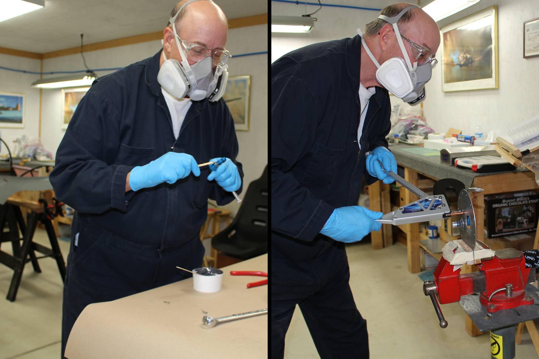
The exterior canopy latch handle as supplied required a lot of additional work. Since I don't have a lathe, I had to set up my drill press work platform vertically to drill the straight level hole for the mounting screw. The 5/64" pilot hole was used to mark the latch tube for match drilling. The latch tube was drilled halfway through, then the pilot hole in the handle was used to help align the parts for match drilling through the tube and into the handle on the other side. The entire hole through both parts was upsized to #30, then the first half of the hole was upsized to 11/64" for screw shank clearance. The deep half of the hole was tapped with an 8-32 bit and the hole entry was machine countersunk to fit the flat head screw. With drilling and tapping complete, the exterior handle was carved and smoothed into an aerodynamic shape.


With the outside handle orientation ascertained, filler was added to the left skirt around the tube and handle base, building up an optimal mating surface. Surface imperfections visible in the photos will be filled and smoothed prior to painting.


Assembly and testing revealed balance problems with the latch handles. In order to pull the canopy open with the aft knob, the open latch hook has to come to rest at an elevated angle so that it clears the retaining boss welded to the windscreen support hoop. If the hook is low when the canopy is pushed closed, the hook will be pushed below the boss rather than above it, making it impossible to latch unless the canopy is reopened. As assembled, the hook wanted to rest horizontally rather than the 45 degrees required. I tried to introduce some stiction into the tube assembly with some heavy grease, but that didn't work. I pondered using springs to hold it open, but that would mean two springs on the latch mechanism, which I didn't want. It would also be difficult to source the right kind, length and size of spring to achieve the goal. Drilling the lightening holes in the hook to shift the balancing point may have helped, but wasn't enough. Perhaps passive counterweight would work. Adding weight to the outer handle wasn't practical, but adding weight to the aft end of the tubular inner handle could be easily done. I drilled through each end of the flat plate of the handle to access the inside of the tube, reamed the aft hole out to match the inner diameter and tapped it for a standard bolt. Pieces of solder and lead shot were inserted into the aft hole and a bolt screwed into the tapped threads with two washers. Then the tube was heated with a torch until the lead melted, settling into the aft elbow of the tube. Testing revealed it still wasn't quite enough weight to do the job... and I could hear some of the lead rattling around loose in the tube. That would never do; I would have to melt more lead and pour it into the forward end with the handle held in a vice at an angle, causing the molten lead to settle in the aft end and sealing the loose bits in place. The hole in the forward end was enlarged and a crucible was fashioned out of a pipe elbow. I melted more lead shot in the crucible with a torch, carefully poured the molten lead into the handle, then heated the handle some more to make sure the lead had settled before hanging it in the small paint booth to cool. Eventually the parts were powdercoated red. More testing proved inconclusive, but the balance of the assembly has definitely been moved aft. I will wait until final assembly approaches before determining if further action is required.


In the meantime, little bits of work on the skirt continued. They were removed, altered and refitted numerous times. Guide tape was laid down, a final trim of the bottom edges was done and the edges were block sanded. The flared-out upper aft corners of the forward top skin were trimmed down; the final edge will be formed by the fiberglass layups on the aft end of the windscreen that overlap the canopy.


In the cockpit, the passenger warning stickers were applied to the right side of the aft cockpit and on the back of the pilot seatback. The windscreen hoop was drilled for the aftermarket grab handles using their supplied jig and instructions. With a small amount of fettling they were securely installed.


I was at the point on the canopy where it would be advantageous to have the canopy firmly attached to the frame, properly aligned, without having to use clecos or more temporary rivets. That would allow independent work on the skirts to refine the fit without having the canopy shift or flex, causing misalignment of the rivet holes. Refining the fit of the skirts had required refilling and redrilling of the rivet holes in the skirt and in the process some of the rivet holes in the canopy were altered slightly. That in itself isn't a problem, but the altered holes needed to be smoothed out before riveting. I didn't want to take the chance of have another stress riser introduced during refitting and riveting that might cause the dreaded canopy crack. Removing the temporary rivets the first time didn't always go smoothly; rivets spun during drilling and a couple holes ended up enlarged enough that they wouldn't hold a #30 cleco firmly. I really wanted to use a structural adhesive (Sikaflex or equivalent) to bond the canopy to the frame permanently while I worked on the skirts separately prior to riveting them in place. Frequent refitting and final assembly of the skirts would leave the canopy unaffected. Lengthy product research on adhesives and sealant that can be used on plexiglass narrowed my choices down to either Sikaflex or 3M AC-251 Black Aerospace Sealant. Sikaflex has been used successfully by many builders, but the application process is a complicated procedure involving careful masking and applying their special Primer and Aktivator (their spelling) prior to the main sealant. Trying to find a single source for all three products proved to be difficult at best. The 3M AC-251 Aerospace Sealant can be used as a stand-alone product, but but bonding is enhanced when using their AC-137 Adhesive Promoter, available in clear and red. Once again, trying to find a source for both materials and was very frustrating. After going through a maze of departments at 3M, I finally reached salesman Cory Gross who sent me a list of distributors and also answered some questions regarding supply. Going through the list of distributors, I learned that most of them are large companies (like Boeing) that will only sell the products in huge lots. Two names I knew and trusted were Aircraft Spruce and SkyGeek. SkyGeek offered combo packs of both the AC-251 and AC-137 in the quantities I needed, but they could only be ordered with a lead time of more than a month. Both suppliers could sell me the AC-251, but Aircraft Spruce did not sell the AC-137 and SkyGeek had only sold it on demand, requiring the long lead time. I decided to order some AC-251 from Aircraft Spruce; initially planning to use it alone. I removed the canopy from the frame, put it in its cradle, smoothed all rivet holes inside and out, prepped the mating surfaces and re-masked the entire inside of the canopy prior to bonding. But after a lot of thought I realized I didn't want to risk applying the AC-251 only to have the bond fail before the assembly was riveted permanently. I needed to consult with 3M some more. Winding through the corporate maze again got me to the voicemail of Aerospace Application Consultant Aubrey Gitter. She called me back within a few hours and gave me detailed product information regarding AC-251 adhesion specifications with and without using the AC-137 adhesion promoter. Bonding strength is more than tripled when using AC-137. I decided to order the required quantity of AC-137 from SkyGeek; it won't arrive until early December.
That's ok; there's still lots of other work that can be done in the meantime, including refits, checks and adjustments. My second canopy interior masking job failed in spectacular fashion; the paper masking tape was not the right material to use to seal the overlays of adhesive plastic sheet, fine line tape and electrical tape. After a few days the paper tape was peeling everywhere. Attempts to salvage it also failed and the entire masking job was removed and redone. Some more shim pads were fabricated and applied as needed and more glassing and filling done along the edge slits.


The occasional warm weeks in late fall provided the impetus to begin working on the wings again in the unheated garage side of the building. Harry Manvel and Curt Martin came over and helped me get the wings out of the wing stand and onto work tables. The first task tackled was to rivet the pitot/AOA mast support bracket to the designated rib of the left wing. The #40 pilot holes for riveting were reamed out to #30 and the bracket was riveted to the rib using MST-42 blind rivets. Moving over to the right wing, the NACA aft cockpit ventilation duct was prepared for installation. Pro Seal was mixed and applied to the flange of the duct. The duct screen was laid flat on wax paper, the duct was pressed onto the screen, capturing the screen with the Pro Seal. After allowing the Pro Seal to set up a bit, more was applied to the screen along the flange and the duct was clecoed into place before riveting with CS4-4 blind rivets. The screen was covered with yellow masking tape and the burrs on the blind rivets were carefully ground flat. The assembly was inspected with a borescope to insure all was well.


The wing and wingtip plans and instructions were reviewed along with the installation instructions for the Garmin GAP 26 pitot/AOA and GSA 28 roll servo. The aileron pushrods secured in the wing for storage were released and temporarily connected to the bellcranks, with padding placed in the innermost rib holes to protect the paint on the pushrods. The left bottom skin was clecoed to the wing and thought given to riveting order. I installed the GSA 28 roll servo in the right wing, torqued and sealed all nuts and clecoed the bottom skin on.


Switching back to the left wing, I worked on finishing the remaining fabrication on the pitot/AOA and mast. The layout of the mounting screw threads was transferred to the mast, the holes drilled and hole alignment checked and adjusted as needed. The pitot/AOA tubes were cut down close to the minimum length; AN compression fittings were placed on the tubes and the tubes flared. Initially the plan was to use the supplied hardware converting from AN plumbing to the pneumatic tube fittings, short polyethylene tubing stubs connected to the tube fittings and elbows, which would then be connected to the tubes routed into the wings from the fuselage. Test fitting showed that, although possible, the routing was less than ideal through the available lightening holes, and trying to use the existing holes for snap bushings in the rib would require the pneumatic to make unacceptably sharp bend to get to the connectors. I purchased elbow AN fittings to replace the stock straight fittings, eliminating the stub tubes and elbows and allowing the tubing adapters to point through the lightening hole with a much better orientation.


A tube guard bracket with holes for snap bushings needed to be fabricated to safely route the pneumatic lines behind the bellcrank without risking any chafing or wear caused by bellcrank actuation. I designed a card stock template and test fit it in the required location, utilizing an existing pilot hole in the spar as one riveting location and determining the layout for the second mounting rivet. The template pattern was transferred to aluminum sheet with some minimal dimension changes; holes were drilled and the piece was cut, bent and formed into the desired shape. The resulting aluminum part need some minor modifications; one rivet hole needed to be drilled in another location to avoid potential contact with the bellcrank and the part was hand-shaped to optimize clearance and fit. It ended up not as pretty as it started but the function and clearances were improved. After using the finished part to match drill a second rivet hole through the spar, it was sent off for powdercoating along with a custom spacer for another assembly and the previously powdercoated outer canopy latch handle which was blemished in the first run. The powdercoater, GT Perfomance Coatings, offered to do all three parts for free as an apology for the original blemished handle. To show my respect for his honorable business ethic, I paid him anyway. It always feels good to do business with someone who cares that much about their customer's satisfaction. The part was fitted with snap bushings and riveted in place on the spar, with a dab of Pro Seal under each tab for added security. Routing spare tubing to the pitot/AOA assembly indicated that the bracket and alignment should work, but I intend to put an anti-chafe buffer on the edge of the lightening hole and perhaps secure the tubes in split conduit secured to the rib with a zip tie to eliminate any potential chance for tube wear. The bottom skin was then clecoed back on to the right wing.


I shifted briefly to the fuselage for more securing tasks. Cable tie adhesive mounts were used to secure the battery cable on the left side of the fuselage between bulkheads. Speaking of which, as I've composed this post I noticed in one photo that I had neglected to do the same thing with the avionics cable on the right side. I just got back in from performing that task this evening. When the aircraft is further assembled I'll have to get at least one more into the tail cone, and it looks like the aft one for the battery cable might not get the job done. I'll probably secure it to the longeron.
The next step addressed on the wings involved nut plates, which were prepped and primed on the tops with grey primer/top coat paint. The bottom skin edges were deburred. The nut plate rivet holes around the inspection cover openings were match-drilled and machine countersunk. The screw holes were dimpled and the nut plates riveted onto the skins.


Many miscellaneous tasks followed. The pitot heat wires were cut to length, terminated and sealed. A grounding lead was fabricated and attached to the adjacent rib. Sections of pipe insulation foam were inserted on the edges of the lightening holes in the right wing to protect he scat tube attached to the NACA vent. I was reminded that I hadn't installed the aft seat eyeball vent yet; might as well get that done. The parts were gathered and instructions sought. Van's doesn't supply much information on the installation of that aft vent, but fortunately Classic Aero Designs addresses it in their instructions on installing the aft stick boot. I'm glad I checked there before starting because they specify modifications to the stock assembly. One corner of the eyeball vent assembly needed to be trimmed away to avoid interference with the aft stick boot cover plate. The Van's vent assembly didn't seem to go together all that well at first; the holes in the eyeball vent and its receptacle didn't match up well and the receptacle didn't nest properly with the support bracket that was part of the front right seatbelt anchor strap. It took some double-checking before I realized that the assembly flanges bolted to the bottom of the support instead of resting on the top of the support as anticipated. Classic Aero Designs provides their own flat head mounting screws for the assembly and their instructions specified that the bracket be machine countersunk for the screws so that the cover plate would lay flat against the bracket. I glued the eyeball vent and receptacle with high-temp RTV; it was the only RTV I have in stock and would do the job. The screw holes in the assembly were much larger than the holes in the bracket, which didn't make much sense. I fashioned short shim tubes to fit around the screws to take up the slack. Attaching the assembly to the bracket was awkward; access was limited and it was difficult to get the washers and nuts onto the screws without dropping them into the space below the cockpit floor. I had to retrieve nuts and washers with a magnetic wand numerous times before grudgingly removing the pilot seat cushions and seatback to improve access. With the assembly mounted, torqued and sealed, I could pop the stick boot into place. The eyeball vent was slightly off center but I could live with it. Reviewing the instructions explained the larger holes in the assembly; that was to provide slack for alignment. Oh well; I wasn't interested in going through the hassle of disassembly to remove those pesky shim tubes. We'll just have to see if my OCD demands it at a later date.


Back to the wings. More nut plates were prepped and painted for installation on the wing root skins. These were for attaching the wing fairings that were fabricated when the wings were fit to the fuselage; they were dimpled and ready for installation. I chose to do two "easy" ones first: the K1100-08 nut plates for the screws that tie the forward and aft fairings together. I match drilled rivet holes, countersunk the skins and riveted a nut plate onto the bottom of each F872BPP aft fairing. It wasn't easy; in fact it turned out to be quite awkward. There was a good reason for this: it turned out to be a mistake. More on that later.


Installing the wing root nut plates was complicated. There were different styles of nut plates required, depending on location; some were standard K1000-08 nut plates, some were K1100-08 recessed for dimpled holes that required a light countersink on the rivet lugs. The aftmost screw hole on each wing required MS21053-L08 offset nut plates. One screw hole near the front spar called for a K1100-08 nut plate, but the location of the hole made it impossible to rivet one tab because it was blocked by the spar. One rivet will work; after all, the screw will actually be pulling and holding the parts together; the rivet is primarily to hold it in place until the screw is tightened. And of course it appeared that I was short on nut plates and had to order more. At every stage I carefully reviewed what I was about to do before I did it because the potential risk for disastrous error was significant. The error I made on the aft wing root fairings was not disastrous, but it was disheartening. The plans detail showed the two fairing pieces and where the nut plate went that linked the two together. That drawing detail didn't illustrate the skin or spar below and that led to my error. Later, when I tried to mock up the assembly I discovered the error and reviewed the plans, which clearly notate that the nut plate was to be riveted to the spar flange, not the aft fairing. The nut plate rivets were drilled out, the screw holes in the spar were countersunk and the nut plates had to be riveted with CS4-4 blind rivets due to access issues. The photo of this looks gnarly but the countersinks and rivet tops were deburred and smoothed out. Fortunately the abandoned fairing rivet holes in the aft fairings would be covered up by the forward fairings. I have to keep relearning this lesson:
READ YOUR PLANS CAREFULLY AND THOROUGHLY!


The wing root nut plates would have to be done in two stages. Since the wings were laying on tables bottom-side-up, the bottom rows would have to be done first. Then the wings would be flipped right-side-up to do the top rows. I started with the K1100-08 recessed nut plates along the forward edges. Screwing the nut plates to the skins with short screws, the rivet holes were match drilled and carefully countersunk. The nut plates and screws were removed, the screw holes were dimpled and the nut plates riveted. I only had three short screws to work with; it wasn't worth cutting more, so these operations were done in batches of three. Sometimes washers were used to allow tightening the screws without getting into the pinched thread locking area of each nut plate. The two offset nut plates had to have part of the edge of the countersunk area ground down slightly to nest with an overlapping skin. Like I said; complicated. When I had all the nut plates riveted on the bottom skins, Harry Manvel helped my flip the wings over so the top side nut plates could be done. When I was finished riveting all the nut plates I was able to flip the wings back over by myself. Another job done.


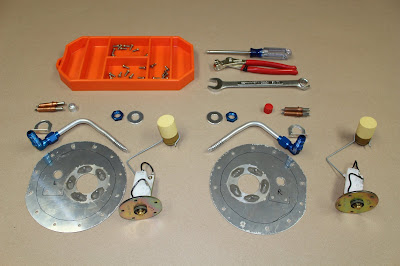
Time to tackle the fuel tank cover plates and senders. Van's ships the quickbuild wings with the fuel tanks essentially completed. The cover plates that incorporate the fuel pickup tubes and the fuel senders are screwed down but not sealed and all other openings taped over. The tasks remaining for the builder include fabricating and installing the fuel pick up tubes, setting up and testing the senders, installing/sealing the cover plates and senders and installing sealing the tank sump drain valves. When these steps have been completed and the sealant cured, the tanks are leak tested before the wings are installed.
After carefully reviewing the instructions and plans, I opened up the cover plates for the first time since the tanks were built. I was greeted by the strong smell of the sealant used during their assembly. I took that as a good sign; if the tanks still held the strong odor of the sealant, it's likely that the tank sealing job was very well done by the factory. I taped up the openings to avoid any contamination of the tanks. The fuel tank sealant used and sold by Vans is manufactured by the Flamemaster Corporation and their brand name for this product is Chem Seal CS3204, but it is commonly referred to among the builder community as Pro Seal, so that is what I'll call it. It is a two-part polysulfide-based compound that cures to the consistency of rubber. It can be purchased in different quantities and packaging systems and should be precisely and thoroughly mixed in a ten-to-one ratio: 10 Part A to 1Part B. Pro Seal is used in many applications on Van's aircraft; as a sealant, an adhesive, or a vibration dampener. It can be nasty stuff to work with and takes a long time to cure completely, but it does its job very well. Like paint components, the shelf life is limited. Expired Pro Seal can still be used for some adhesive or vibration applications, but sealing demands a fresh batch. I had some expired Pro Seal in stock but ordered more from Van's in preparation for the upcoming work.
The first step undertaken was to separate, shape and smooth the anti-rotation brackets used to help hold the fuel pickup tube assembly in place. The brackets are delivered as a stamped-out angle that comprises four brackets. Van's supplies material for four brackets to provide the option for inverted fuel; I will not be installing an inverted system so I only need two brackets. With the brackets prepared, the rivet holes were final-drilled to #30 through the brackets and cover plates. Fuel pickup tubes were fabricated as shown on the plans. At this stage I wanted to practice assembling these components; some steps involve Pro Seal and are done in a precise sequence, so it is imperative that the process is fully understood, all the parts are correctly prepared and the work done smoothly and methodically.


The stock fuel senders are float-type; they are sold in left-right pairs that can only be installed in the correct tank with the correct orientation. Since they can be used in many different aircraft, the float rods need to be correctly configured for the RV-8 tanks. The rods are cut and bent to specified lengths and shapes before snapping into place on the fuel sending units. Before being installed, the senders should be tested either with a power source and gauge or with a multimeter to check resistance range. The range specified by Van's was 32 ohms to 240 ohms; mine checked out at 31/248, so they passed. I temporarily zip-tied the senders to the cover plates and rehearsed for final assembly. I also cut out card stock covers that could be removed and replaced much more easily than strips of tape.


While gathering the hardware for the fuel pickup tubes, it came to my attention that I seemed to be missing some of the AN fittings required; one elbow and two nuts (insert joke here). This led to a thorough review and reorganization of my parts inventory. It's not uncommon during the process of building to have to use parts in one assembly that may have been intended for another, so I ordered replacement parts. While awaiting their delivery, I installed the Velcro strips that would secure the aft seat cushions, practiced assembling the left skin with pitot mast for riveting and connecting the pitot heat wires with the skin in place. To make that connection easier, I drilled a hole in the pitot mast support bracket and installed a grommet in the hole. The pitot heat power wire will be fed through that grommet, simplifying the routing and connection.


When the replacement parts arrived, the fuel tank work resumed. The senders were removed from the cover plate and the fuel pickup tube was temporarily assembled with the anti-rotation bracket clecoed in place. I put the covers back onto the tanks and used a borescope to examine the inside of the tanks to check the position of the fuel pickup tube. The goal was to get it as close to the bottom of the tank as possible without touching the skin. A slight adjustment for each tube provided optimal placement. The plates were removed and the paper covers placed over the openings. A gentle attempt at screwing down the senders revealed some thread chasing would help. Nut plates are designed with slightly pinched threads that will grab and hold a screw in place without lock washers or jam nuts. But in this application, used in conjunction with Pro Seal, it's more important to be able to tighten the screw down smoothly with less resistance from the nut plate, letting the Pro Seal do its job. Van's had installed and sealed all the nut plates for the covers and senders. The cover plates screwed on easily and after a light chasing with an 8-32 tap the sender nut plates were more cooperative.


I was still waiting for the Pro Seal to arrive and I needed to find something else to do on the airplane besides canopy work. So I built a rudder simulation jig that attaches to the fuselage and allows the rudder pedals to work somewhat normally without the empennage assembled onto the fuselage. And of course that led me down another creative rabbit hole that ended up with me creating another "show" on my YouTube channel. I could explain it and show pictures, but it's easier just to share a link here. Sure... it's four minutes and twenty three seconds of your life you won't get back... but if you're reading this right now, I'd guess you can spare the time... and you'll probably enjoy it.
Useless Projects Show 01
Not only that... but after Steve Thorne saw it, he asked me for permission to use some
of my clips in the latest episode of his wildly popular FlightChops channel. Check this out:
How Much $$$$ Lumber to Build a Metal Airplane? Lesser-known Costs - VLOG 11


of my clips in the latest episode of his wildly popular FlightChops channel. Check this out:
How Much $$$$ Lumber to Build a Metal Airplane? Lesser-known Costs - VLOG 11
Ok; back to building. I wanted a visit from my EAA tech counselor Dan Jones before the bottom skins were riveted on. It took awhile to schedule - after retiring, he's busier than ever as a consultant - but he came by and gave the fuselage, engine and wings a thorough inspection. We discussed some of my concerns and he made some helpful suggestions, such as making sure all my AN compression fittings for oil, fuel and air lines were marked with torque seal paint after final tightening. The same applied to all locking nuts on any adjustable rod bearings on any control pushrods. Those of us who have seen, heard or read Vic Syracuse discuss that topic have that rule indelibly burned into our memories. I did have my control pushrods dialed in, but they will be checked again after final assembly, then torqued and sealed. Same with fuel/oil/brake fittings; I'll have filling, bleeding and flow testing to do before they be tightened down permanently and marked with torque seal paint. Overall it was a good visit. He answered all my questions, we got a chance to catch up and his appraisal was highly complimentary. We'll plan the next visit when the engine is ready to be started again.


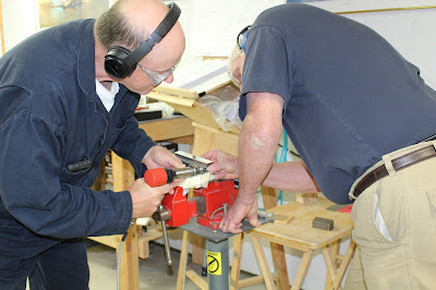
The Pro Seal arrived the same day Dan visited. The next day was tank closing day. I prepared the shop by warming up the unheated garage side of the building with a propane torpedo heater, then opening up the shop connecting doors and turning up the shop heat to maintain the a decent temperature in the garage. The parts were carefully laid out and all mating surfaces were prepped and cleaned. The fuel pickup tubes were snugged up to the AN elbow fittings and aligned. The first batch of Pro Seal was mixed and the trickiest part of the assembly begun. Due to tight clearances, the tube, fitting, bracket and cover plate all had to be brought together at the same time, with Pro Seal applied to all mating surfaces. That meant applying the Pro Seal, getting the fuel elbow loosely assembled on the cover plate while the anti-rotation bracket was brought up into loose position. Then the tube nut was tightened until the hex points meshed with the stamped shape of the bracket, allowing the bracket tab to sit flat on the cover plate with the rivet holes aligned. Clecos secured the bracket; the outer washer and nut were tightened up to secure the assembly. Then the cover place assembly was placed in the vise and the bracket rivets were squeezed with the Main Squeeze riveting tool, using the narrow access yoke. It took several careful attempts to properly squeeze the larger round-head rivets. The assembly was done one cover plate at a time, then Pro Seal was added and smoothed in each location. With both fuel tubes and brackets assembled to the cover plates, the remaining mating surfaces on the plates were cleaned again. A second batch of Pro Seal was mixed and applied to the outer mating surface of the left cover plate. The cover plate was joined to the fuel tank; an awl was used to begin aligning the screw holes as each mounting screw was dipped in Pro Seal before being inserted through the tank skin into the nut plates. The screws were gradually tightened in a star pattern before a final torque down and double check. This entire process was repeated on the right tank. Then the mating surfaces of the sender plates and cover plates were re-cleaned. A third batch of Pro Seal was mixed and applied to the left sender plate. The float was carefully inserted into the tank and the sender plate was affixed to the cover plate in a similar manner to the cover plates, with a few subtle changes. Alignment was more difficult to ascertain as there was more play in the assembly and there was only one correct alignment for all five screws. The upside to that was that there was no way to accidentally misalign the float arms. The uppermost screw had to make metal-to-metal contact with the sender plate for ground continuity, but the screw threads had to have enough applied Pro Seal to be leak-proof. At the suggestion of other builders, I replaced the standard 8-32 screws with stainless steel socket screws. These would be much easier to manage if a sender ever needed to be replaced. That entire process was done to the left sender, then repeated on the right sender. All torques were checked and the Pro Seal beads supplemented and smoothed. Some minor cleanup in non-critical areas was done, and the the tanks were closed. I will allow a longer curing time due to the cold conditions in the garage before doing a tank leak check, and the tank sump drains won't be installed until after the wings are back on the airplane again. Not many photos of this process; careful assembly with Pro Seal was a much higher priority.


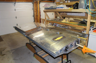
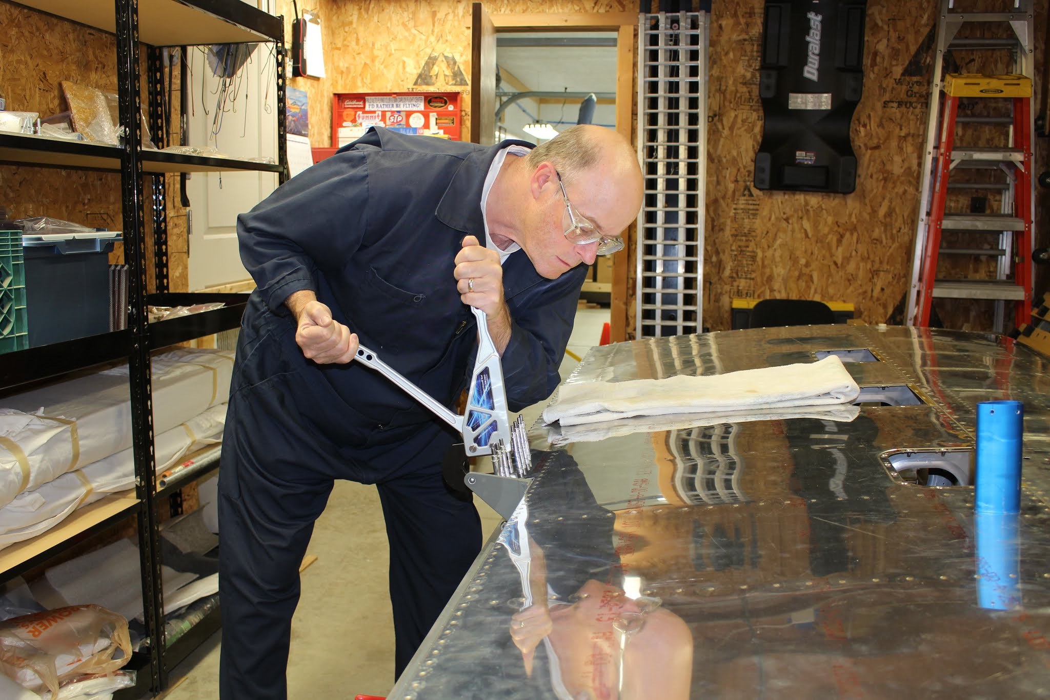
At long last, the time had come to rivet on the bottom skins. I really wanted experienced help with this job. I had conferred with other builders, some of which had done their own wings. I knew it was possible... but I knew I'd be much better off with someone helping. I had put out feelers before my tech counseling, and I was surprised when Dave Pohl remarked in an offhand way that he'd be glad to help. Dave is a fellow PTK pilot who built his RV-9A that's been flying for 15 years now. With the tanks and inspection done, I sent him a text letting him know I was ready. That same day I had to do things at the hangar, and whenever I'm at the airport I'll wander up to Echo Row to see what's cooking. Between E and F rows there are at least five RV aircraft that I'm aware of; they're all friends. As it turned out, Dave had gone flying with Ted that morning in Dave's aircraft and had just returned. Ted was about to leave in his own aircraft and Dave was still doing his post-flight routine. He said he didn't mind getting started that afternoon, so we headed to my house and jumped right in. We worked on a simple practice project to get our team chops dialed in before getting started on to the right wing. It should have been the easier wing because there was no pitot mast to contend with... but we had a bit of a learning curve (and relearning curve) ahead of us. I knew how it was supposed to go, but I had no wing experience. Dave had experience, but it was long time ago. It took us a little while to find our rhythm. As a result of incorrect sequencing, there was one area that we just couldn't buck two rivets, no matter how hard we tried. I had to ream the holes to #30, do a very light machine countersink and use Cherry Max blind rivets to secure the holes. You have to work at the aft inside and work your way forward and outward. Once you get past the first three bays, the work gets easier and you can really chug along as a team. We worked six hours each that first day and got most of the right wing done.


We probably would have gotten more done if I hadn't slowed Dave down with my OCD fiddling and annoying him with taking photos. I think it got to us both a bit; we started getting punchy and hamming it up for the camera. I got us started... (WARNING: QUASI-EXPLICIT CONTENT)


Dave got me with that third photo. I thought we had played it straight that time...I didn't know until I uploaded the photo that night. You can see the cropped photo in the previous group that I kept for the official archives. We joked about it on social media; Dave suggested that if I was going to photoshop him, I could at least make his hair brown and make him look younger. Challenge accepted.

Dave wanted to get started at 9:00 the next morning; that sounded good to me. I got out to the shop at 8:00, got some tidying done and squeezed a handful of solo rivets along the flap hinge line. I also working on improving the skin suspension system we had tried the day before. I clamped two C-clamps to an overhead joist, hung each end of a tie down strap from each C-clamp and secured the hooks with zip-ties. The strap wrapped below the skin to lift it up, but that method didn't work well and we had abandoned it. The second day I laced a string through every other rivet hole in the end of the skin and slipped a length of PVC conduit through the string loops, evened up the loops and taped them down with PVC tape. Two separate straps were used to lift each end of the conduit, thereby lifting the skin. The angle of the pull could be changed just by moving the wing table to a different location below the C-clamps. It worked pretty well. In a few hours, the right wing was finished. We took a long lunch break in the house and I bored Dave with some of my warbird exploits and videos. We got back to work and didn't stop until the left wing was done. It went smoother than the right wing because we learned from yesterday's mistakes. The pitot mast and the support bracket took some figuring, but we got them done. As evening arrived we were both tired, but we both wanted to finish the job, so we kept going through dinnertime until the left wing was finished around 7:30. We took a couple of final photos, then Dave went home to his understanding wife. I went inside to my understanding wife who had dined alone; I did the same before going back out to the shop, squeezing the last of the solo rivets and doing some reassembly before calling it a night. Dave worked 9 hours that day; I put in 11 hours. A very long day for us both, and we were both hurting the next day... but we were glad it was done. I thanked Dave profusely and I now owe him several tons of favors. I hope I get a chance to repay his kindness, expertise and dedication, but like many builders he just remembered how much help he got on his build and was glad for the opportunity to pay it forward. I know I'll feel the same way someday.


The next day I did a couple small projects. The inspection covers for the wings that had been patiently sitting on the shelf for years were dusted off, relabeled and installed on the wings. Turning my attention to the fuselage, I addressed an issue that I've pondered since the airplane has been on its landing gear. I've wanted to make a wooden work platform that would emulate the height and angle of the wing when the airplane is on the ground that could be positioned next to the cockpit. It would allow me to get a feel for getting in and out of the cockpit with the wings on. It seemed like a side project too large, expensive and unnecessary to seriously consider. But after staring at the airplane and my existing work stands for a few minutes thinking about ways to work around the problem, I came up with a solution that was simple, quick and effective. Stacking the smaller stand on the larger stand with the aft pair of legs folded and the forward legs resting on the first step of the stand below created a platform that was close to ideal. Strapping the legs in place made the compound stand very sturdy and stable. The first time I climbed onto it, I was struck by how tall the airplane is on its gear. I've always known that was the case, but now I could really get a sense of how big the completed airplane will feel... and that felt pretty cool! I practiced getting in and out some more, and decided to finish up a few remaining cockpit details. I grabbed my Bose headphones, kneeboard, flying hat and iPad from my flight bag and brought them into the shop. I had purchased a 3-D printed holder for the Bose headset control module and determined the best placement location for it in the cockpit. The holder is attached with industrial Velcro which was applied to the right bulkhead cap. Plugging in the headphones and playing with the orientation and height helped dial in the finished installation. I could now simulate an actual ingress and egress routine; where and how to situate the kneeboard, headphones and iPad prior to getting into the cockpit, gearing up prior to engine start and post-flight exit. While in the cockpit I practiced blind switch/control location memorization and got to check out the rudder simulator with my feet. This was a fun and useful diversion that made me realize how close I'm getting to having a finished aircraft. There is no stronger motivator than having the finish line in sight.


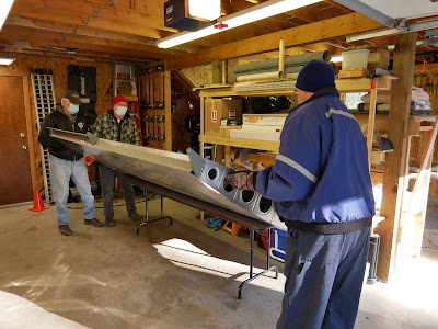
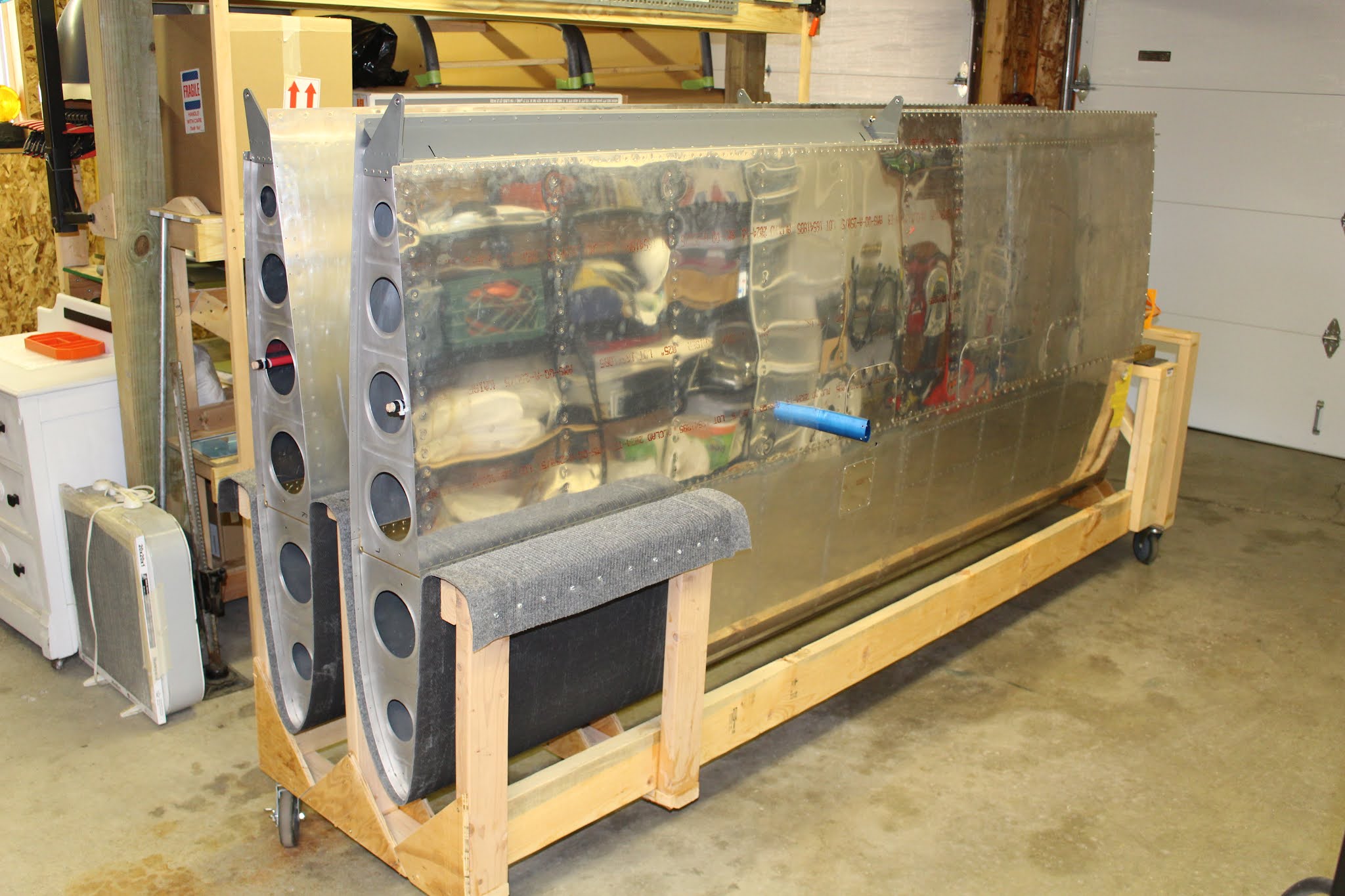
With the wing skinning finished, they needed to be placed back in the wing stand. It will be easier to work on the wing tips with the wings held vertically. The weather is starting to turn wintry, and I had to wait to choose a nice calm day to gather allies for the task. Fellow Chapter 113 brethren Joe Kirik, Tom Smith and Shunsuke Shibata volunteered to help. Shunsuke showed up at 9:00 a.m.; Joe and Tom arrived together a few minutes later. We shared coffee and I gave them a brief tour before we opened up my garage bays and got the wing stand positioned. The actual transfer only took about ten minutes; the empty work tables were folded and put in my Yukon. We wheeled the wing stand back into the garage and took some photos. I was planning to take the tables to the hangar and offered my friends a hangar tour since it was on their way home. They accepted the invitation, and I got an extra favor out of Tom by having him drive the Yukon to the hangar for me while I led the caravan in the Mustang. I was planning to get the Mustang to the hangar for winter storage, and this made that process much simpler for me. Now I didn't have to worry about getting a ride home from the hangar; I could park the Mustang and drive the Yukon home. I enjoyed being able to share the hangar and show off the empennage on its stand. In normal times I would have treated them all to lunch... but with Covid back on the rise, we chose discretion. I thanked them all profusely and they headed on their way. Later that evening, Shunsuke shared the photos he had taken that morning and I'll share some of them here.


In actuality, I drove the Mustang home that afternoon. The next morning I took it to the car wash and picked up some some hardware store supplies before returning to the hangar. I topped off the tank, stabilized the fuel in the tank and gave the car a quick wax and wipe before covering it for winter. The Toyota station wagon was also taken for the last ride of the year before getting a fill up and gas treatment before covering. I did a little more puttering in the hangar before heading home.
That brings us to the present. I set a few days aside to complete this blog post and do a few more pre-winter chores. The next airplane work anticipated will be working on the wing tips until the 3M AC-137 Adhesion Promoter arrives. The winter will be spent finishing the canopy and windscreen. When spring returns the paint booth will be set up and painting will commence until the fuselage, wings ailerons and flaps are ready for the milestone trip to the hangar. That is still a LOT of work... but I am really starting to realize how close I'm getting, and that's pretty exciting. Stay Tuned!