It's official: 2020 was not good. It could have been worse... but definitely not good.
After stowing the wings back in the wing stand, work was begun on the wing tips. Trimming the aft inner edges for aileron bracket clearances, the fitting process began with taping the wing tips onto the wings and match drilling the #40 pilot holes through the wing tip mounting flanges and the wing tips were clecoed in place to check, then removed. The ailerons were brought out of storage. Each aileron was mounted to its wing, aligned with the aileron jig and held in place with PVC tape. The wing tip inner aft edges were further trimmed to clear the ailerons with a 1/4" gap and clecoed in place. The aft edge wing tip/aileron alignment was checked for each wing. Both wing tip aft edges drooped slightly low; about 1/4" average. No correction will be done until after the wing tips are checked during final assembly. All pilot holes were upsized to #30; the wing tips were removed and the screw holes in the wing skins were final-drilled to #28, deburred and dimpled.


Van's published Service Bulletin SB-00031 in November regarding a manufacturing error in some earlier quickbuild fuselage kits. Rivets were installed instead of the mandated AN-3 hardware in the engine mount bracket/lower longeron assemblies. Fortunately my aircraft had the correct hardware installed, so a difficult fix was avoided... this time. The future would tell a different story.

With the initial wing tip fitting done, the ailerons were wrapped up and placed back in storage. Wing tip fabrication continued with installing nut plates along the flanges. To facilitate this process I made up a couple of tools: a countersink gauge and a countersinking brace that incorporated a vacuum to catch the fiberglass dust produced in the process. This inspired another one of my silly videos; this one addresses some of the many stands and jigs I've made in the course of this build. Since making the video, I've thought of more I'd created... and also made a few more. Such is building... it never ends. The video describes the process of installing the nut plates; more details are on my Kitlog Pro site.


The next wing tip work would involve the landing/taxi and nav lights. Using the template supplied by AeroLEDS, the holes for the adjustment screws and landing/taxi lights were drilled and cut. The large openings are cut undersized, then sanded to conform to the lights. The sides of the lights are wrapped in tape to protect them during fitting. The nav light mounting surface needed to be sanded flat and smooth on both wingtips. A centerline was established and drawn on the surface and the mounting brackets are used to lay out the screw holes and positioning. The instructions were a bit vague on this so I checked photos from other sources to make sure I was doing it right. With the screw holes drilled, the rivet holes were drilled for the nut plates that hold the mounting brackets were drilled and countersunk. The best location for the wiring harness hole was determined and drilled with a 5/8" hole saw. Riveting the nut plates to the wing tip surfaces was tricky; a couple rivets could be squeezed but access was inadequate for the rest. I debated on using blind flush rivets but didn't want to enlarge the rivet holes in the nut plates. I ended up carefully bucking the rivets with a light touch on the rivet gun, and it worked out well with no damage to the fiberglass. Test fitting the nav lights revealed the need for some shim material to be placed underneath the brackets to allow the lights to be locked in place by the brackets. I used PVC tape to test fit, then cut proper shims out of gasket material for final assembly.


Attention was switched to the wing tip light lenses. Similar to the canopy, the lens material is supplied in one piece which is cut in half and gradually trimmed to fit the recesses molded into the wing tips. Another bit of fabrication that I needed to sneak up on; marking, trimming, sanding, re-marking, re-trimming, more sanding; check fit, sand, repeat... and eventually they fit as intended. The nut plates for the mounting screws were laid out and riveted into the corners of the lens recesses. One nice thing about working with clear plastic is that once the lenses fit the wing tips, it was a simple matter to lay out the mounting screw holes by sight, carefully making the pilot holes by hand-turning a long #40 bit before final drilling to 5/32"and countersinking the holes. The left lens was fitted first and all steps repeated for the right lens. I was pleased with the end fit, but not so pleased in the notch I had gouged in the edge of one of the recesses while countersinking for the flush rivets. That would be a pain to patch and smooth, but at least it would be on the bottom surface of the wing tip and not in plain sight. With the lens fabrication completed, they were wrapped up and placed back in storage.


During all the wing tip work, I allowed myself the distraction of figuring out how to fit the seat harnesses. This took some research and I learned that the harness bolt bushings installed by Hooker would need to be trimmed back to fit into the Van's mounting brackets. I also had to order two more bolts, as Van's didn't include hardware for mounting the crotch straps. Once figured out, the harnesses were placed back in storage. At least I understand the process now, and all parts are gathered.

Fitting of the landing/taxi lights resumed. To facilitate the rest of the fitting, I made a wing tip inversion jig that would hold the wing tip on the bench with the opening facing up.


The openings for these lights had to be enlarged quite a bit from their original template shapes. At times I wondered if they would be able to fit correctly at all; there was no extra room between the adjustment tabs and the inner sides of the wing tips and the nut plate rivets were an additional obstacle. It seemed like I'd have to sand so much of the outer corner away that it would end up cutting away too much of the surrounding material. I made a 93 degree card template that would be used to set the landing/taxi lights to the correct angle. More sanding was required on all the edges of the openings to fit the lights well enough for the outer corner pivot mounts to nest on the inside of the wing tips. These pivot mounts can either be riveted in place with all-aluminum blind rivets or molded into place with flox; I chose a sort of hybrid between the two. When I was satisfied with the placement of the pivot mounts, I used a long #40 bit to match drill mounting holes and clecoed the pivot mounts in place. Flox was applied as a thick fillet around each mount. When that flox had cured and the parts were securely held in place, I removed the clecos and filled the holes with more flox, then backfilled the inside cavities of the pivot mounts to blend with the flox filling the holes, further bonding the mounts securely. The rough areas of the fillets were knocked down and the exterior hole patches were sanded and smoothed. The divot in the recess edge was also patched with flox. The wing tips will need some additional work, such as fitting the end ribs and sanding and smoothing prior to painting. But this work will wait until final assembly; for now, my wing tip work was complete. The lights and wing tips were placed back in storage.


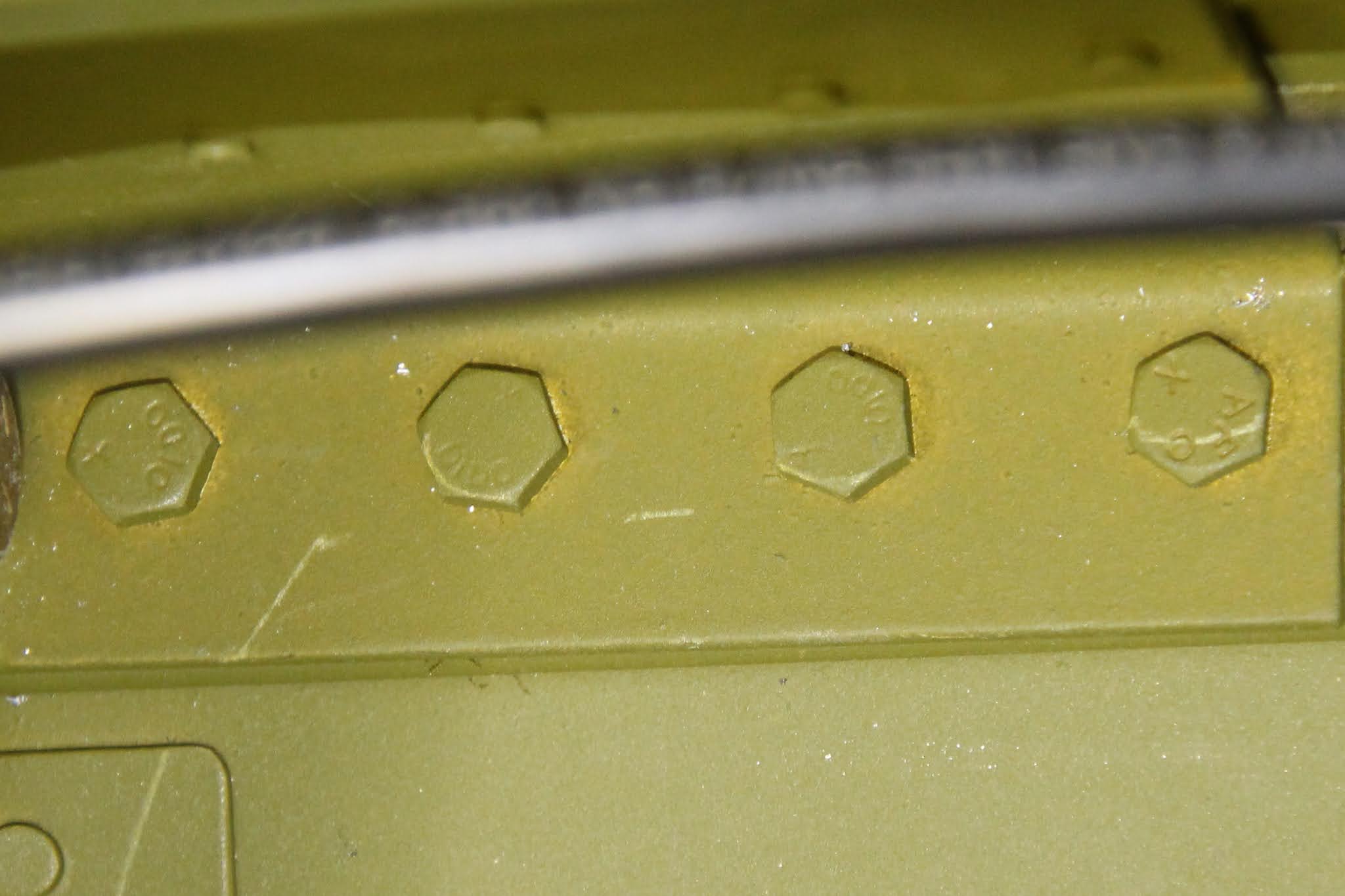
Then, on December 11, the building progress on my beloved RV-8 took a huge blow. The FAA released AD 2020-25-12. Here is a link to the PDF file: FAA AD 2020-25-12 I'll not get into too much detail here; you can read the AD for that. Basically it states that some Superior Air Parts crankshafts in Superior and Lycoming O/IO-360 engines have a forging flaw that has caused three of them to break. The FAA proposed this AD in the beginning of the year, and after a lot of investigation they made it official, effective January 15, 2021. Based on certain part numbers and serial numbers, designated crankshafts in currently airworthy aircraft must be replaced within 25 operational hours of that date. 192 crankshafts are affected; of those, 77 are in experimental aircraft. I noted the part and serial number ranges affected and compared them with the numbers on my crank. Bingo:

To say I was devastated by this news would be a gross understatement. The $30K engine that was fully installed in my aircraft had a bad crankshaft that had to be replaced. After I unwrapped from the fetal position and wiped the tears off my face, I began to reach out to the building community to see what my options were. AD compliance with experimental aircraft is complicated, and I don't want to get into all those details here. But I wondered about when I should do all this unthinkable work. Would it be possible to wait until after my first startup or even after my first flight, given the 25 hour leeway? My DAR Ted Gauthier informed me that I did not have those options. Because my aircraft was not yet certified as airworthy, it must meet all current ADs prior to inspection. He suggested I remove it and get it fixed as soon as possible. I had immediately contacted Rhonda at Barrett Precision Engines and informed her of the situation. She would contact Superior and determine how this would all work out, then get back to me and we'd set a plan in motion. My fellow aviators were all very supportive; many of them had gone through similar situations. Yes, it is a big setback, to be sure... but maybe not as big as I may be thinking... and it's much better than having my engine self-destruct in flight. There are also some minor improvements that can be made during the process; in any case, my aircraft will be better off when the work is redone. Some very large questions still need to be answered regarding cost and logistics. I know Superior and Barrett are both honorable companies that stand behind their work and their products, but I don't know how hard this might hit me financially. The FAA estimates that the cost of this repair would come in at around $15,000. I don't currently have the resources to muster anywhere near that amount of cash. Logistically I'm also in a bind; getting the engine back to Tulsa, rebuilt, and back home to Michigan is complicated by the fact that I no longer have the Ford F-250 pickup truck that made the first journey. My current rust-bucket Yukon, which I refer to as the Pukon, is not trustworthy enough for such a trip, and renting a truck for the time and miles required would get very expensive. I'm told I may have local options for the rebuild... but I would really prefer to have Barrett do the work. I'll have to see how all this plays out, but in the meantime there is a lot of work to do.
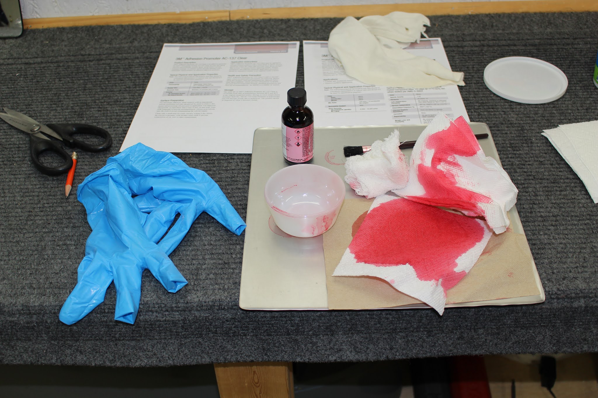
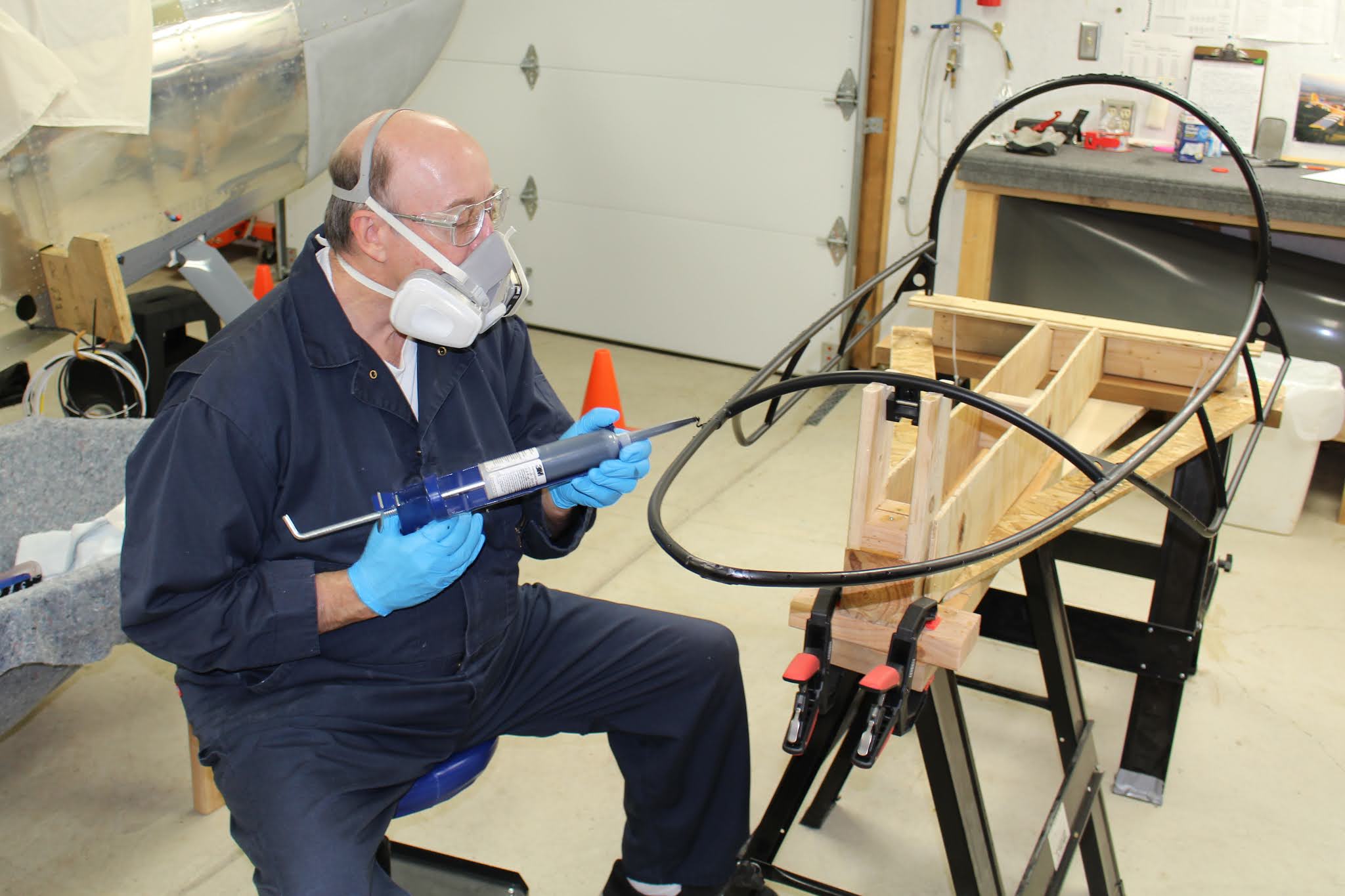
Before I jumped into the engine work I needed to wrap up some loose ends. The 3M AC-137 adhesion promoter finally arrived after a 6 week backorder, which meant I could finally bond the canopy to the canopy frame. After I applied the adhesion promoter to the canopy and frame, I mixed the AC-251 sealant and applied it to the frame along the joint line delineated by the rivet holes. Curt Martin, Harry Manvel and Leo Knowlden assisted in the assembly by holding the canopy off the frame while I aligned the rivet holes and clecoed the canopy into place, squeezing the canopy into the sealant. After allowing the assembly to cure for a few days, I countersunk the holes in the plexiglass along the forward canopy hoop, removing and replacing the clecos one by one to keep the assembly as stable as possible. I dipped each AAQC-4-4 blind rivet in freshly mixed sealant before squeezing them into place from the top center down in pairs, wiping any excess sealant off the canopy and squeezer as I went. The bottom rows of clecos will stay in place indefinitely until the time comes to resume work on the canopy skirts.


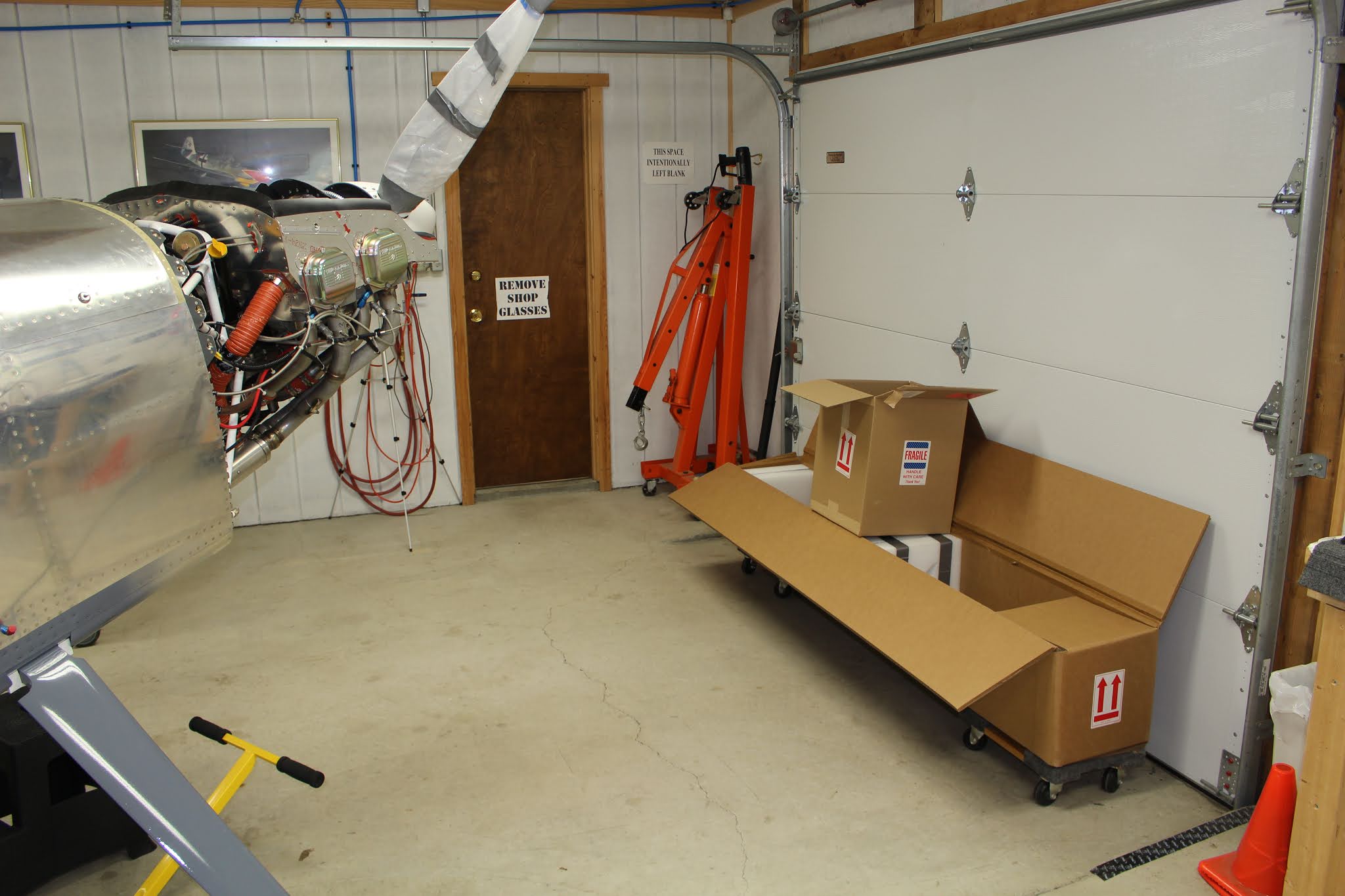
Still reeling under the onus of the AD, I forced myself to begin preparation. The garage area was cleaned and cowling jigs set up on paint stands to cowling storage. The engine table had to be retrieved from the hangar before a winter storm came to town; an annoyingly complicated affair. The Mustang had to be uncovered and moved out of the way and the empennage stand rolled out. Other jigs and junk needed to be moved to get the table out to the front of the hangar. The empennage and Mustang were put back, then the enclosed trailer was lowered off the jacks, attached to the Pukon and pulled outside. The table was loaded into the trailer and strapped down; the hangar was closed up and the table brought home and offloaded into the detached garage. The trailer was brought back to the hangar, detached and raised back onto the jacks. The hangar was locked up again and I made it home just before the snow fell. I was happy to have completed the task in time. It would be one of the rare glimpses of happiness this month. After the canopy work had been done, I had cleaned and rearranged the shop, moving the fuselage to the optimal position for engine removal. I removed the cowling and took a lot of photos to document the current state of assembly, trying hard to not be overwhelmed by the magnitude of the work to be undone. A few days later with better weather and the snow melting, I walked the table over to the shop side and gathered various boxes for the spinner, prop and other engine accessories.


I started off by removing the spinner and prop. This was much more awkward than before because of how tall the RV-8 stands when the tail is on the ground. The fuselage had been leveled when I had installed the prop for the first time. It didn't take too long before the prop and spinner were both packed away and placed in storage.


Apparently my run of bad luck wasn't finished with me yet. My laptop decided this would be a good time to die. No data was lost (I store everything on a separate hard drive) but all my programs were on a machine that seemed to run ok, but would only display a flux of vertical colored lines. The only files at risk were some time lapse video clips of the prop removal stored on the internal D drive. A call to HP Omen Support revealed that it was probably a hardware issue (duh), that the computer was out of warranty (d'oh!) and that the fix would cost around $550 (damn). I had already ordered a cheap new laptop in a panic when the fault occurred, and I wasn't going to throw that kind of money at this old lump that had been struggling to meet my demands for a while now. I continued to test the machine, taking advantage of a moment of clarity to get the prop files onto a thumb drive. I tried connecting to our TV to use as a monitor and that seemed to work; apparently the failure was in the laptop screen. I ran out to Office Depot, bought a cheap monitor and set it up, and now I'm getting by on the life support it provides. Don't know how long this will last before something else goes wrong with this wounded soldier... but I'm hoping it holds out at least until the end of the year or until this post is published, whichever comes first. Not looking forward to setting up a new laptop, either; that's another huge pain. But at least I'll have it available so I won't have to feel so naked and afraid without my systems in place.


Nothing left to do now but face the inevitable. As Samwise Gamgee said to Frodo in the Lord Of The Rings: "...there's nothing for it...". I never understood that phrase; another British axiom that seems contrary to me... but it stuck in my head as I faced my treacherous and terrible journey to Motordor. I just don't want to go there... but go there I must... so here goes.
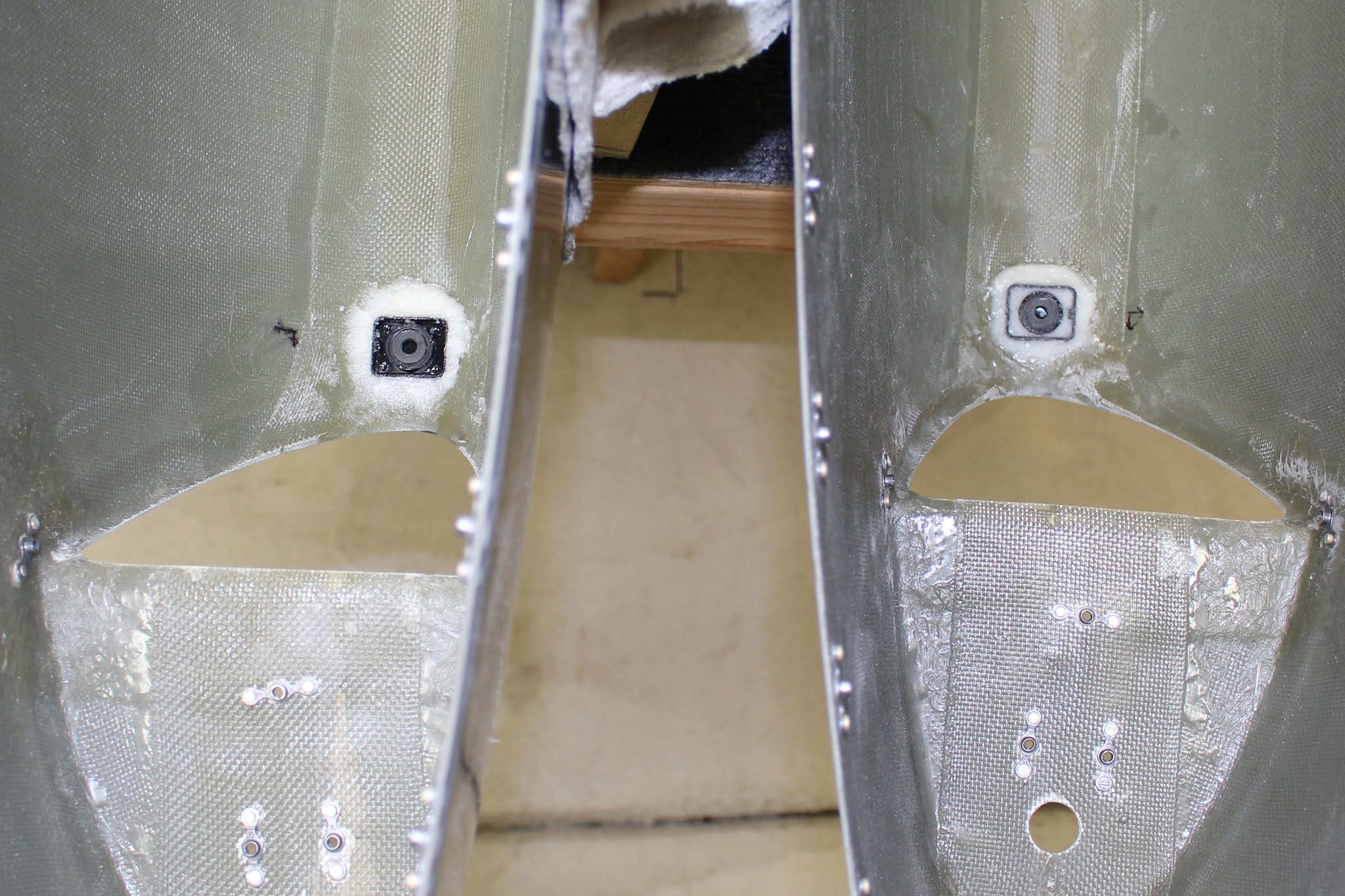
Nineteen hours of work spread over four working days saw the removal completed on Christmas Day. Itemizing the tasks would take up pages, but I worked from the front end aft, detaching and/or removing components, brackets, wires, hoses, tubes, nuts and bolts. It was definitely stressful having ot undo so much fiddly work, knowing it would all have to be redone. The baffles were a particular challenge due to a couple shared rivets holding parts together that had to be drilled out, and the Permatex Ultra Black sealant applied around the engine perimeter of the baffles was much tougher to release than the Hi Temp Red used in some locations. For the right aft baffle assembly I had to resort to using safety wire as a wire saw to cut through the heavy applications in some areas. But the baffle components were removed undamaged. I kept a list of items that would need to be replaced during the rebuild, such as star washers and gaskets, and also started compiling a list of tools that should be included in a future aircraft toolkit. There were a few fortuitous situations regarding the engine removal. I had been advised that placing fire sleeves around the control cables for the throttle, mixture and prop would prolong their life but I initially chose not to do so because I didn't want to face the hassle of having to detach the cables. With the engine out, it will now be easy to do. I had suspected for a while now that I might have an oil leak on the back side of the engine. That was confirmed during disassembly; there was some oil on the inside of the bottom cowl and during dismantling I found oil on the exhaust pipes. With the engine hanging from the hoist it was much easier to do a full examination to determine where the oil was coming from. I was surprised to learn that the oil was not coming from one of the components or fittings I had installed, but it appeared to be dripping off of three separate bolts along the back sides of the bottom engine case. It was difficult to say whether it was leaking around the bolts themselves, or whether it was leaking along the case seam in two areas, but it did appear that there was no oil leakage occurring above the seam. It would seem that the original assembly was not completely oil-tight, and that was a surprise. I began to think about many detailed instructions I would have to give to Barrett regarding disassembly and reassembly. There was accessory attachment hardware I was leaving on the engine that I wanted to keep in place such as nuts, bolts and washers. The mixture linkage bracket and other longer-than-stock case bolts needed to be reinstalled exactly as found. I'm really hoping I will be given the chance to oversee the rebuild just as I had observed the original build. It remains to be seen whether or not that will be possible. I was lucky that most of the sensors attached to the engine were able to be removed without having to disconnect the wiring. I took a lot of photographs of the dismantling, and all the work was also captured on time lapse video. Now I can say I know how to remove the engine from my aircraft. Combined with the photos taken during the initial assembly, I shouldn't have too much trouble reinstalling the engine properly, if not better than the first time. It won't be nearly as easy as disassembly, but it won't take nearly as long as the initial buildup. I also learned a few tricks in the process, like the wire saw technique of splitting the sealant bead in otherwise inaccessible areas. Safety wire also came in handing for removing the cotter pins on the lower engine mount castle nuts. The engine cases have recesses cast into the engine mount bosses for the washers and nuts that complicate cotter pin insertion and removal. To install, the pins must be fully inserted with the bolts clocked in one position, then the bolt is rotated so that the cotter pin head is inside the recess and the other ends can be wrapped around the bolt end. Access for removing the bottom two cotter pins is very tight, but I was able to thread a long piece of heavy safety wire through the eye of the cotter pin. The long ends of the wire were routed upwards above the engine, tightly gripped with locking pliers and the pins were neatly yanked out from above. With everything detached and the cotter pins removed, I enlisted the help of Dave Farquharson to remove the engine mount nuts and bolts and hoist the engine out after removing one fuel pump fitting that wouldn't clear the engine mount tubes. After the post-removal examination and sealing a few remaining fittings and case openings, the engine was placed back into its foam nest atop the engine table. I need to order more hose plugs and clamps for some of the flared fittings that have been taped over temporarily, and I'll need to lift the engine again to install some of them, so for now the engine is covered loosely with plastic sheet and the engine hoist is kept handy. But for now, my work is done.


The time lapse video has no soundtrack, voiceover or explanation; only a visual record.
RV-8 Engine Removal
With the engine and components sorted and stored, the wiring and cables dangling from the firewall were bundled, zip tied and covered. The shop was rearranged and prepared for more canopy work.


That concludes the build work for the year 2020. Amy is having rotator cuff surgery tomorrow and I'm sure that will keep me out of the shop for at least a little while. Once this post is published I'll need to do a complete data backup and set up my new computer... another dreaded task. What a cluster of a year this has been... but a lot of progress was made. I look forward to the day when the aircraft is flying and all the frustrations and setbacks will fade to insignificance. I'm still convinced this aircraft will fly in 2021... Stay Tuned.