This is going to be another long entry that will cover an interesting mix of miscellaneous and momentous activities. Let's begin with some miscellany. I made up the wiring for the flap motor and continued working on the baggage door. Since I didn't purchase my ignition key from Van's and they don't sell the baggage door lock separately, I bought a cabinet lock from the hardware store. They're standardized and it fit fine... but as it turns out, the actual lock wasn't clocked correctly to use the lock arm provided by Van's; the square hole that fits the lock peg was clocked 45 degrees off where it needed to be. The simplest solution was to duplicate the lock arm out of spare stock and cut the square hole with the right orientation, so that's what I did. It didn't take long and I was pleased with the result. I also had to fabricate my own locking washer out of thin stock with bendable tabs to hold the ring nut that retains the lock assembly. I assembled the all the lock components to the door including the pins and snap bushings and torqued, sealed and safety-wired as necessary. I probably should have waited until after I had painted the edges interior green... but I'll probably just paint the inner door skin instead. That skin can't be riveted until the top forward skin is riveted in place because the door has to be fit to the finished skin opening before the inner door skin is blind riveted from the inside of the fuselage. I did a trial fit with the top forward skin clecoed in place and I don't anticipate too many fitting issues, but getting the locking pin blocks riveted to the bulkheads and blind riveting the inner door skin with the top forward skin riveted in place will be a real pain. Riveting the top forward skin won't happen until after final assembly at the airport, so the door will be set aside for awhile.


While I was waiting for the date of the initial wing fitting, I did some ancillary carpentry work. I had previously cut down the legs of the fuselage stand in preparation for fitting the wings, but I realized that I also had to cut off the tops of the leg posts so that they wouldn't interfere with the fitting. I also made up a stand that would hold the horizontal stabilizer vertically for painting.


Now for the momentous. I prepared for the wing fitting by making up some temporary spar pins out of hardware store bolts, cutting and grinding off the threads and coating them with motor oil. I also removed the vent line plugs and cut the fuel lines to approximate length. Four of my friends from PTK came out after our usual Saturday morning breakfast to help fit the wings. Ted Gauthier, Terry Kohler, Dave Pohl and Curt Martin assisted with the fitting, and it went very well. I couldn't resist assembling the empennage as well; I wanted to see it looking like a real plane for the first time. Later on, after hanging and rigging the ailerons and flaps, I could do a complete controls check. That would prove to be a wise decision.


The next step is one of the most important parts of assembly: setting the wing incidence. (Disclaimer: the following explanations should not be construed as instructions; consult your builder's manual and other resources; your results may vary.) A few special tools are required to get this done. A carpenter's level must be fitted with a spacer block of precise dimensions and glued at a prescribed position. A drill guide must be fabricated to assure the rear spar bolt hole is drilled straight, and the hole must be precisely placed to assure correct edge distance. After double checking the fuselage to make sure it is perfectly level, the wings are squared off to the fuselage and aligned with each other. Two plumb bobs are hung from the leading edge of each wing; inboard and outboard. A guide string is pulled tight along the floor along the leading edges and under the plumb bobs to determine the relative alignment of the wings. To square the wings, measurements are made from the tip of the wings at the main spar to a center point established on the aft of the fuselage; I used the center of the tailwheel fork pivot axle. Even with the main spar anchored to the spar box with the four bolt pins, the wing can be adjusted slightly in all directions because the rear wing spar is sandwiched between the forked aft fuselage spar. The wingtips may be moved fore and aft to align the wings and the aft wing spar can be moved up and down to set the incidence. Once dialed in, the rear spar is held in place with clamps.


I made up some templates for the spacer block and drill guide blocks and brought them to my local machinist at Doc Fang Engineering. I initially requested two different drill guide blocks; one sized to the #30 pilot hole and one to 9/32". The holes would then be reamed out to the finished size of 5/16". Doc ended up fabricating the spacer block and one drill guide out of aluminum stock. The drill guide used a press-fit bushing for drilling the pilot holes; the bushing would be removed for the undersize holes and the finish reaming would be through the block as well as the spars.


The angle of incidence is dialed in using the modified carpenter's level. The modified carpenter's level is placed with the front end edge setting directly over the main spar web and the edge of the spacer block directly over the aft spar web. With the fuselage level, the wings squared up and the modified carpenter's level in place, it should also read level. It is wise to check all measurements, dimensions and levels multiple times to make sure everything is as close to exact as it can be. There are some tolerances allowed, but the closer to exact the specs are, the better the airplane should fly. The final measurements for each wing are made with the drill guide clamped to the rear spar and forks, holding everything in place tightly. When I was sure I got everything right, I drilled the #30 pilot hole in the right wing. The bushing spun a couple times and had to be reset, but the hole was drilled straight and the spar and forks were secured with a #30 cleco. Repeated the process on the left side; same issues, same results. While the block was still clamped to the left side, I removed the bushing from the block and drilled the hole out to 9/32" before reaming the block, spar and forks out to the finish size of 5/16". I removed the block and bolted the left side with a temporary bolt, washer and nut. Moving back to the right side, I realized I had created a problem for myself. I had planned to use a #30 drill bit as a locating pin to reset the block and bushing into alignment. But now the block was reamed out to 5/16"; the bushing was now loose in the resized hole. I had to shim the bushing with scotch tape to reset it in the block. I figured scotch tape was the thinnest shim material available and would do the best job of getting the bushing centered in the reamed block. It worked well enough to get the block, forks and spar aligned with the #30 drill bit. Then the drill bit and bushing were removed and the hole drilled to 9/32" and reamed to 5/16". Again, removed the block and clamps and bolt in place.


Double checking all the measurements and levels confirmed that my incidence was set correctly. The next step was making the fuel tank attach brackets out of a large chunk of aluminum C-channel. This was fun fabrication, carving two mirror-image parts with interesting shapes and angles. I was happy with the way the parts turned out, but when I went to fit them I realized I had made a mistake. Focusing on the blueprints, I drilled the holes for the fuselage attach bolts where I thought they were supposed to go. I thought they would be used as drill guides to match-drill the fuselage. Since that area of the fuselage was built at the factory (and I didn't read ahead in the directions) I didn't realize that the fuselage already had the holes and I should have match-drilled the brackets using the fuselage holes as guides. Checking the fit I realized I had gotten the holes very close to matching, so instead of having to make two new brackets I could touch up the holes just slightly to get them to work. Great idea... but having the wing in the way meant the work had to be done with the angle drill attachment, and that's where the nightmares began. To make a long painful story short, I broke a few bits when they bound up; some broke off in the fuselage and had to be tapped out from the inside with a punch. Trying to get access to do this, I climbed into the fuselage... but I didn't have enough clecos in the floor and ended up bending two floor panels slightly. On one hole the bit moved the part and the hole was started in the wrong place. Fortunately I only drilled through the skin; there were enough unharmed layers of angle and gusset beneath that to keep this from being a huge disaster. New bits were ordered, the floor panels were removed and straightened and eventually I ended up with two working fuel tank attach brackets that would bolt to the fuselage. In retrospect, I think that match-drilling the holes from the fuselage would have been somewhat difficult because of their location being surrounded by various obstructions. All's well that ends well, I guess.


There was more fitting work to be done on the brackets, but after all the errors I needed a break from them so I moved on to other errors. It didn't take me long to realize that I had gotten myself into the traditional shipbuilder's conundrum. It's an old tale where someone builds a boat in their basement... then has to excavate and knock down a foundation wall to get the finished boat out of the basement. I had gotten the wings fitted successfully in my shop with about a foot clearance between each wingtip and the adjacent wall. What I had somehow missed (written in bold lettering in the instructions) was that if I had limited space around the wings, I should have placed the aileron/control column pushrods inside the wings before they were fitted. Even with the bottom skins off it was impossible to get the 3' pushrods in from underneath. They would have to be passed into the wings from the ends. I had three options: 1) assemble the crew again, remove the wings, get the pushrods in place and reinstall the wings; 2) drill two holes in the adjacent walls and pass the pushrods through the holes and into the wings; 3) drill one hole in one wall, pass one pushrod through one wing, through the fuselage and into the other wing, then pass the second pushrod into the first wing. My right wingtip was adjacent to an interior wall; the left wing was adjacent to an exterior wall. I wasn't worried about penetrating the interior wall because it separated my shop and my garage areas; it could be easily patched and I didn't care about how it would look as long as I could get the job done. However I wasn't so keen on penetrating an exterior wall, so I decided to use option 3. This turned out to be another nightmare. Getting the hole drilled in the wall in the right place and the right angle was easy enough, and the location worked out well for both sides of the wall. But passing the pushrod through the fuselage turned out to be much harder than I thought it would be because of the dihedral in the wings. I had to remove the control column assembly to get the necessary clearance; a lot of awkward and difficult work I thought I wouldn't ever have to do again. Even then, the dihedral made getting the pushrod from the right wing through the fuselage and into the left wing only just barely possible. With both pushrods in each wing, the control column had to be reassembled (grrrr) and the hole in the wall had to be patched. Again.... all's well that ends well, I guess... dammit. Another painful learning experience that inspired a suitable meme.


Holes needed to be match drilled between the wing lower inboard skins and the center bottom skins. The instructions suggested taking measurements and doing a hole layout on the wings prior to fitting, but I elected to use a strap duplicator. The locating pin of the duplicator was placed in the #40 pilot holes in the wing skins and the matching holes were drilled in the center bottom skins. #40 clecos were fitted in all the holes; one by one the holes were upsized to #30 and fitted with #30 clecos, then all clecos were removed. The right side holes were done first, then the left side; the fuselage needed to be moved slightly right and left on the fuselage stand to gain access to all the holes in each wing. Access was tight underneath the wings but the job got done.


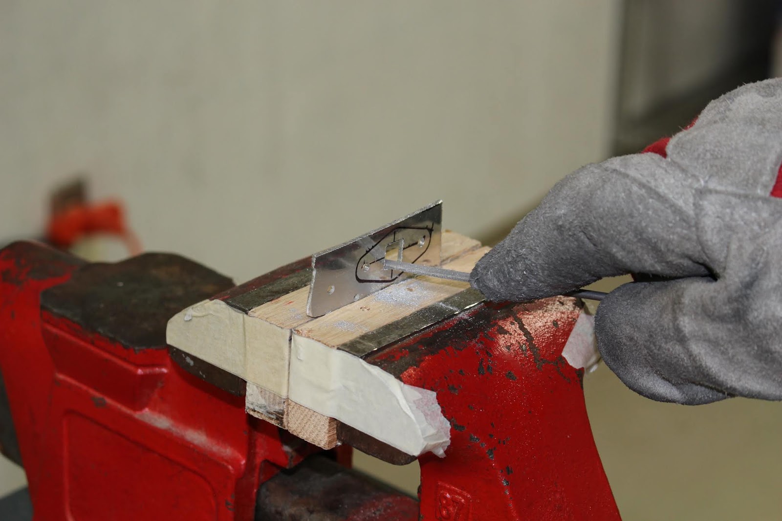
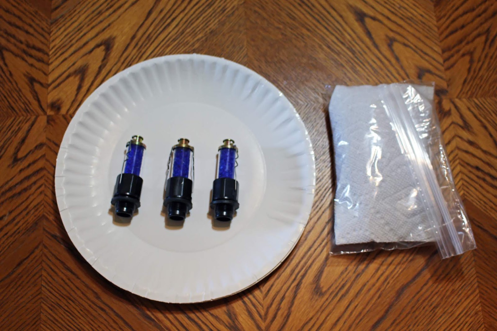
Another small task that needed attention was changing the desiccant in the dehydrator plugs I had installed in the engine's upper spark plug holes. Michigan has had high humidity this spring and summer and it didn't take long for the blue desiccant to turn pink. I purchased more desiccant, changed out the old for the fresh reassembled the plugs and put them back in the engine. I also dried out the expired desiccant by baking at 350 degrees for 3 hours as recommended by the manufacturer, and it turned a fresh blue color again. Fun with chemistry. Also interesting was that I only had to change the desiccant on three of the four plugs. The #1 cylinder valves were both closed so no humidity had entered that cylinder; that desiccant remains a fresh blue color.

The fuel tank attach brackets needed to be bent slightly to fit flat against the angles attached to the fuel tanks. Judicious clamping and forming with hardwood blocks, locking pliers and a mallet got them in the right shape. When that was done, another somewhat critical bolt hole needed to be drilled through the tabs and brackets. Care needs to be taken to assure that the hole is drilled in a place where minimum edge distance can be maintained. I marked the outline of the angle tabs on the brackets and did a lot of measuring to determine the best location for the bolt hole. I drilled a #40 pilot hole in each bracket with the drill press, then bolted the brackets to the fuselage and match drilled the holes through the angle tabs. Then the holes were gradually upsized to 1/4" in four increments to make sure the finished holes would be straight. Two temporary bolts were installed to check fit, which looks good.


The next task was fabricating vent lines that would connect the wing and fuselage vent lines. This was a pretty straightforward job but they required some careful hand bending to fit properly. Although only two are needed, I did end up making three of them... more on that later.


It was time to install and rig the ailerons and flaps. The control sticks were centered upright in the fuselage and the aft stick was secured to a wooden brace clamped to the aft armrests to hold the sticks in the centered position. The aileron bellcrank jig was put on one of the bellcranks and the respective aileron/control column pushrod was adjusted to fit; the process repeated on the other side. Then the ailerons were hung and the aileron/bellcrank pushrods were attached. Before the flaps were hung I needed to fabricate flap actuation pushrods. I had to order more tube stock to complete this task as I had used up some of my supply for other purposes and didn't have enough left for two pushrods. I also seemed to be missing one jam nut even though the checked inventory indicated it was there. Oh well... just another hardware store run. The first attempt at fitting the flaps revealed that the inboard edge of each flap top skin would need to be relieved to clear the fuselage skin. The inboard bottom skins required trimming to fit along the edges of the center bottom skin of the fuselage. The flap pushrod holes in the fuselage would also need to be enlarged to clear the pushrod rod end bearings. The flaps came off and went on many times before this was all completely dialed in. The flap actuation weldment was reinstalled in the fuselage. The flap motor was run with the 12 volt battery to place its pushrod in the fully retracted position and it was attached to the weldment and fuselage which would place the flaps in the fully extended position. The left flap pushrod was attached to the actuation weldment and the flap motor was activated to fully raise the left flap. The flap pushrod was then adjusted so that flap and aileron trailing edges were aligned. I followed the same procedures for the right flap. Eventually I had both connected and was able to run the flaps through their full travel.


I knew I would need to test the actuation with the floor panels in place; I had to check the clearances of the pushrods through the floor holes and the flap actuation weldment would be sitting slightly higher on the floors. But first I worked on the wing root fairings, trimming them and bending them into the required shapes for initial fit. The fairings were match drilled to the wings and clecoed in place.


Before installing the floors, I cleaned up the flap wiring harness a bit. Floors went in; flap motor and actuation weldment installed; flaps connected; run flaps; disconnect; trim holes; reconnect; run; disconnect; trim; reconnect; repeat numerous times until all clearances were good.


More trimming of fairings; fit; trim; fit; trim; etc. Fitting the forward wing root fairings was tricky, getting the bends right and fitting them tight enough to reach all the matched holes top and bottom. The process was complicated by interference from the fuselage stand; the fuselage was shifted to and fro again to get access to all the holes.


One aspect of rigging that I had not addressed yet was seeing how the aileron and flap alignment would compare with the aileron/wing tip jig in place. When I did the initial fitting of the flaps and ailerons on the wings when they were on tables, I used the bellcrank jig in conjunction with the aileron/wingtip jig I had made for the purpose. I only built one jig and the wooden fixture that held the aileron was removable; it would be flipped from one side to another depending on which aileron was being aligned. I needed to make sure that each aileron was held in the right place for correct flap alignment, so I went back and jigged each aileron with the stick centered to check flap alignment, first on the left wing, then on the right. Things looked pretty good; there might have been a very slight stick displacement to the left, but I could dial that in on final assembly.
The next step was making the flap fairings. More fun fab, and another learning curve... literally and figuratively. These pieces had some matched holes but some had to be match-drilled from inside the fuselage, working blind with an angle drill. As a result one hole was mis-drilled, but I can plug it by lightly setting a headless rivet and filing it smooth. There's enough edge distance that it won't interfere with the correct rivet hole. A lot of careful hand forming was needed to get the fairings to fit properly. I learned the best forming techniques for these parts working on the left fairing and refined them on the right fairing. As a result, the right is a little bit better than the left, but they're both acceptable.


Once the wing root fairings had been initially trimmed and fitted, they needed to be marked for additional trimming. A 3/16" gap was required between the inboard edges and the fuselage skin to allow clearance for the rubber trim pieces that would be fitted during final assembly. I found the easiest way to do this was to find some shim material that was 3/16" thick; I ended up using a plastic drill bit guide. Starting on the top and working my way forward and around to the bottom, I laid the guide against the fuselage skin and scored the skin with an etching tool, repeating the process step-by-step all the way along the edges, first for the right wing then the left. I used the etching tool instead of a marker because I could be more precise with it. I was marking a cut line; the scratch in the aluminum would be rendered irrelevant. The actual trimming would be done later.
I wanted to fit all the floors and front seat and do a complete control check from the cockpit before the wings would be removed. I installed the front seat flooring and seat ramps, and had a couple problems. These pieces need to be removable so they are fitted with screws into nut plates. Nut plates are designed to bind the screws and they can be very tight sometimes. Running a tap in and out of nut plates is not recommended, but another way to make the screws go in more smoothly is to use beeswax or Boelube. I used Boelube on each screw I installed and also used my new electric screwdriver that has an adjustable clutch to prevent stripping. Most of this installation went fine... but two screws decided to cause trouble. One screw in the front corner stripped out its Phillips head very easily and couldn't be tightened or removed. Another screw for the left seat ramp bracket stripped out its threads inside the nut plate... again, very easily; even though the screwdriver clutch was on a light setting. I dealt with the stripped head by carving a slot in the head with a Dremel tool and cutting disc so I could remove it with a standard screwdriver. I did my best to protect the metal around it (of course it had to in a corner), and only put a small mark in the floor panel. It was a dirty job, but I got the screw out and replaced it with a new one that I tightened by hand The stripped screw in the nut plate would have to wait for now.


I decided to take advantage of some hot weather and get the initial cut done on the canopy base. I did it with the Dremel tool and diamond cutting wheel. The factory had marked some cursory lines around the base as a starting point for removing the base flange from the canopy bubble. I made these initial cuts the way I'd seen it done in various videos, with the canopy upright and sitting on the flange. But I wasn't able to get the cutting wheel right down into the corner where the mark was, so I got as close as I could. In retrospect, what I should have done is invert the canopy and found a way to nest and brace it so I could cut from the bottom. But it's cut now, and time will tell if it will work, or if I've made a very expensive mistake. I also should have cut it outside; it's a very messy process that took a while to clean up.


Back to control connections. Since I wanted to check all controls and rigging, I thought I should also connect the elevator trim tab. When I tried to get the cable in place, I discovered that I had lost some slack somewhere; I couldn't get the cable out far enough to assemble it correctly. This required some detective work and a lot of fiddling; removing the rudder, vertical stabilizer, right elevator, elevator pushrod and baggage floor; disconnecting the cable from the vernier; trying to reach the cable from the outside by reaching through multiple aft bulkhead holes... lots of real pains. I figured out that when I had secured the static lines to the cable I had pulled the cable forward a little, so I had to squeeze into the aft fuselage to cut the zip ties securing the static line. Lots of extra work, but I got the slack back and was able to reassemble and reconnect everything.


This was a good time to have another condition inspection done by my tech counselor, Dan Jones. I wanted to have him do an overall inspection, check the rigging and discuss some potential issues. We discussed my rudder travel and cable slack issues and came up with a couple potential solutions. Overall, he was happy with the rigging, but it looked to him that I had my rudder spaced out too far from the vertical stabilizer. He suggested dialing in my rod end bearings to get the rudder leading edge closer to the rear spar of the stabilizer. This would bring several benefits: better airflow around the rudder and more slack available on the cables. I made the adjustments the next day and was very pleased with the results.


Inital wing fitting was now complete; the next stage would be final disassembly. Before removing the wing root fairings, I drilled out the mounting holes to the finish size of #19 for attachment screws. Once removed, I took care of trimming the 3/16" off of the wing root fairings, deburring and smoothing the edges, corners and screw holes. The wings will have to have the nut plates for the fairings riveted on before final assembly. This was a good time to address another issue. Remember when I mentioned having to make three fuel vent lines? That was because when I was match drilling the #40 pilot holes on the right forward root fairing, I accidentally drilled into the right fuel tank vent line. I knew that was a potential issue; I tried to avoid it, but it had happened anyway. I made up the replacement and got it fitted. The empennage components, flaps and ailerons were removed and stored.


Now to face another problem waiting in the wings... or actually, waiting in the fuselage. The floors needed to come out again, which meant addressing that stripped screw in the nut plate that held the left seat ramp bracket and left console cover in place. I tried to back it out, and the nightmare became real. The screw would not go in or out; it just spun in both directions. With the threads stripped in the nut plate and good threads protruding out of the bottom of the nut plate, the screw was basically a big rivet holding two parts to the fuselage. Those parts had to come out, and the screw couldn't just be drilled out because it would spin with the drill bit. The head of the screw had to be cut off at the expense of the parts below. GRRrrrr... not happy... but I did what I had to do. What a mess. I got the head cut off and the parts came apart, but the left seat ramp bracket was wrecked, and the console cover below it was damaged... and the remnants of the screw were still lodged in the nut plate. I tried knocking it out with a punch and failed, but at least that got it set tight enough that with some sloppy drilling, more punch tapping and wiggling the exposed stub like a loose tooth I was able to extract it. The damaged nut plate couldn't be removed because of it's built-in location, so I ran a #19 bit through it to clean up the hole. When the replacement bracket is installed during final assembly, that one screw will have to be a longer replacement secured from underneath with a stop nut. The damaged console cover was straightened; I'll have to smooth it out with a little filler and repaint it later.


Final disassembly continued with removing the flap motor, actuation weldment and flooring. The vent lines and fuel tank attach brackets were removed. Rivet holes were laid out and drilled into the tank attach brackets; two large nut plates were primed on the bottom and riveted to the brackets for the bolts that secure the brackets to the tank angle tabs. Pilot holes were drilled through the brackets for safety wiring and other potential future modifications if inverted fuel lines are ever used. A quick test fit and the brackets were removed again. Four of the eight bolt pins were removed from the main spars and the rear spars were unbolted. A makeshift net was laced in between the instrument panel and the forward baggage bulkhead to hold the wiring in the fuselage while inverted; other loose components were secured. The wings were now ready for removal and the fuselage was ready for flipping.


It took a couple of tries to get a crew together, but the wing removal went smoothly. They were placed in the wing stand and stowed in the garage area. We flipped the fuselage onto the work platforms so I can install the landing gear legs permanently, mount the com antenna on the belly, get the flap fairings riveted in place and a host of other tasks. My gratitude is extended to Joe Kirik, Bruce Breisch, Dave Buck and Joe Fredericks for their able assistance.


That brings us to the present. There will be a two-week break in the building now; I've got to get ready for the trip to OSH later this week and I'll be there for the whole event again this year. Business will be conducted, discussions will be held, photos taken and fun had. I bought a new lens for the camera that will eliminate having to switch lenses and increase my zoom capability. Initial tests are a little inconclusive... hoping to get some great shots this year. There are a few more surprises in store this year, too. Stay tuned!