April was a busy month, and May continues apace. I purchased the Complete Airframe Tool Package from Cleaveland Tool, and practice projects from Vans Aircraft. I ended up with four practice projects. Project 1 is a cellphone stand that came with the tool package, project 2 was the Vans toolbox, and projects 3 and 4 are Vans classroom projects; 3 is a riveting practice piece, and 4 is a basic airfoil buildup. I also ordered a sheetmetal training video and aircraft painting book from the EAA Store. In mid-April, just as I was ready to start working, I experienced a rush of self-doubt that put me in a slump. It was almost as if my brain was calling my bluff. After all this dreaming, wishing and waiting over more than a decade, was I really going to be able to do this? Dreaming is easy... but building an airplane is a lot to learn, and a lot of hard work over a long time. Could I trust myself to stay the course, follow the long learning curve, and actually build, finish and fly my own aircraft? I'm sure most builders go through this, but I must admit it spooked me. Once I actually started working, however, that feeling subsided. I just took it one step at a time, and was encouraged by the results.
After finishing up a large music archiving project and getting caught up on house chores, I started work on project 1. I tried to make the first project a microcosm of the whole process: prep work, drilling, deburring, dimpling, painting and assembly.


After the paint was dry, I checked my work. My coverage was not perfect; I learned that I needed to be able to manipulate the parts as I painted them, rather than just try to paint them from a hanging position. I figured I'd move on to assembly, and respray the completed part.
My very first experience with riveting was at a two-hour sheetmetal workshop at OSH in 2010. Although I didn't exactly follow their directions correctly, my actual riveting quality was ok... but that was because their rivet guns were set up properly. When I began assembly of project 1, the squeezed rivets turned out fine... but the back-riveting was a disaster. I had not set up my gun right; despite adjusting and testing, it had too much air, and too much power. When I tried using the back-riveting set it went berserk, smashing the hell out of the rivets and skittering across the part, chipping paint and bending metal. I was a bit disheartened, to say the least. Here's the result:


I decided to leave the finished stand as-is, as a testimony to my errors. Lessons learned from practice project 1: Prime your part properly the first time; get proper coverage before proceeding; don't complete your painting prior to riveting; set up your rivet gun properly; finish painting after assembly.
After completing project 1, I built up the C-frame table... and learned a few more things in the process. I didn't read the materials list on the instructions carefully enough; they called for 3/4x2-1/2 lumber but I used standard 2x4s with actual dimensions of 1-1/2x3-1/2. I cut all the pieces to the lengths they specified, and assembled the frame. When I laid the plywood over the frame I saw the dimensions didn't match; I re-read the instruction sheet and discovered my error. The width was correct, but the frame was an inch and a half deeper than the plywood. I thought about disassembling the unit and recutting the cross-members, compensating for the increased thickness of the lumber... but it didn't seem worth it. If I centered the plywood on the frame, I only had 3/4" of nicely rounded 2x4 extending along the front and back edges, which posed no functional problems, and the piece was much stronger than it would have been with the thinner lumber, so I left it as it was. I notched the back for the C-frame post; drilled the hole for the rivet/dimple sets; covered the top, front and back with carpeting and added two handles to make it easier to move around. After experimenting with the finished table, I added a filler piece of plywood that can be inserted underneath the C-frame to raise the lower pad for different rivet/dimpling sets.


After completing project 1, I built up the C-frame table... and learned a few more things in the process. I didn't read the materials list on the instructions carefully enough; they called for 3/4x2-1/2 lumber but I used standard 2x4s with actual dimensions of 1-1/2x3-1/2. I cut all the pieces to the lengths they specified, and assembled the frame. When I laid the plywood over the frame I saw the dimensions didn't match; I re-read the instruction sheet and discovered my error. The width was correct, but the frame was an inch and a half deeper than the plywood. I thought about disassembling the unit and recutting the cross-members, compensating for the increased thickness of the lumber... but it didn't seem worth it. If I centered the plywood on the frame, I only had 3/4" of nicely rounded 2x4 extending along the front and back edges, which posed no functional problems, and the piece was much stronger than it would have been with the thinner lumber, so I left it as it was. I notched the back for the C-frame post; drilled the hole for the rivet/dimple sets; covered the top, front and back with carpeting and added two handles to make it easier to move around. After experimenting with the finished table, I added a filler piece of plywood that can be inserted underneath the C-frame to raise the lower pad for different rivet/dimpling sets.


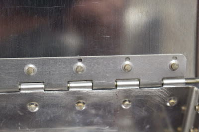
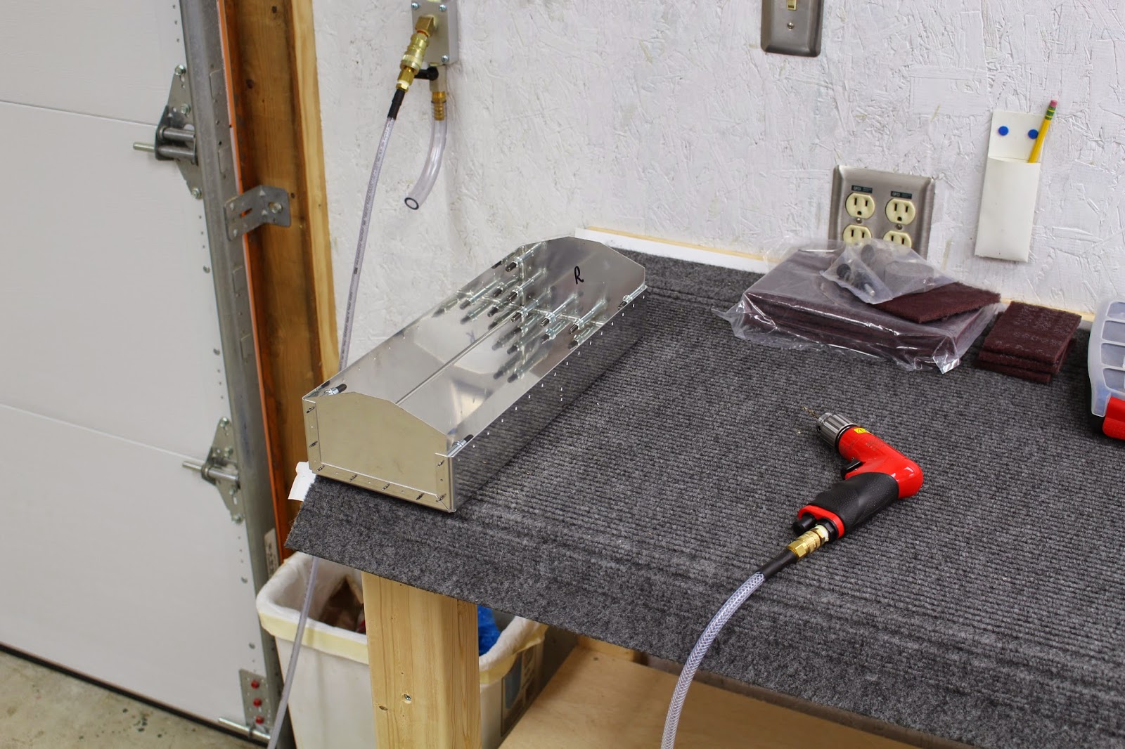
Then I started work on project 2, which was the infamous Van's toolbox. I decided to do this as an unpainted project, so it went fairly quickly. I was much happier with my riveting on this project; I got the gun dialed in, checked all my rivets with a rivet gauge, and found them to be decent. But with every new project, there are new mistakes. The first came with the hinge. On the first lineup, I clamped it in place on the box, but instead of marking the holes and seeing where the marks lay on the hinge, I drilled some test holes, which turned out to be way off the center of the hinge flange. Since the box side of the hinge is exposed, and the lid side of the hinge is hidden, I flipped the hinge so the errant holes would be hidden inside the lid. The directions said to align the box edge with the hinge eyelets. Since it would be very difficult to do a test fit because the lid flange is on the inside, I merely aligned the center of the eyelets with the box edge, match-drilled and set the rivets. Afterwards, I test fit the lid... and realized the box edge was impinging on the lid flange, and wouldn't let the lid close completely without flexing it. The most practical solution was to file down the box edge where the lid flange eyelets contacted it. This took awhile... but it worked well enough. In retrospect, I shouldn't have taken the directions so literally, and lined up the box edge with the bottom of the eyelets, rather than the center. I should have also done more to achieve a test fit... maybe taping the hinges in place first would have worked. The second problem came with the latch. Riveting the latch bottom was difficult due to the two rivets being so close together, and the limited space for the rivet gun set. The result wasn't pretty... but it was acceptable. Despite being very careful with my hole layout on the lid for the hook, after riveting the hook into place I found that the latch wasn't very tight because the hook should have been just a bit higher. This is the problem when you have to rivet things together that would have been better off being bolted, which would allow for some fit adjustments. My solution was to wrap a small piece of electrical tape around the latch loop, taking up the slack and making it a smooth, snug fit. The final issue was applying the Van's Aircraft decal to the lid. I did my best to lay it on center-first and spread it out smoothly, but I still ended up with a few air bubbles underneath the decal that could only be purged by poking the bubbles with a pin and squeezing the air out. The decal is flat... but because it's clear, you can still tell where the air bubbles used to be. Oh well... it's only a practice project that served its purpose well, and I will definitely use it to hold some of my aircraft-specific tools. Lessons learned: test-fit parts first, even if difficult; mark and check before drilling new holes; read instructions very carefully; grow a third hand to apply decals.




 Project 4 is shaped like an airfoil section. It is designed to familiarize the builder with forming and assembling a Vans control surface, although its design is a bit different from most actual airframe components. It is a fairly straigntforward project with only 12 parts, but the details of construction and order of assembly are important.
One of the things I've agonized over during the planning stages of building my aircraft is the nebulous subject of painting. I've done a considerable amount of research on the subject, but it's hard to reach any firm conclusions. When it comes to priming and painting, there are so many different opinions on what to use, what to do and how to do it that I found it hard to decide on a game plan. Even Vans says, in effect, that you can do what you want, because there are so many variables it's impossible to say one approach is definitely the best. The only consistent opinion is that any aluminum material that is not alclad really should be at least primed. I've seen builders that prime all their interior surfaces, some that only prime ribs, stiffeners and the skin areas where parts come together, and some do away with priming any alclad parts because they figure that the possibility of corrosion becoming a significant issue during their own lifetime isn't very likely. I intend to continue my research before deciding my own plan of action for my aircraft, but in the meantime I decided to try different approaches while building these practice projects to see if the experience would help solidify my own opinions on the matter.
To that end, I decided that on project 4 I would prime the spar, trailing edge wedge, ribs and stiffeners and leave the interior sheet aluminum unpainted. After assembly, I would mask off the ends and prep, prime and paint the exterior as though it were one of my own control surfaces.
The plans called for me to make three tools; a slotted hardwood block for edge forming, a relatively thin bucking bar with a countersunk dimple-forming pattern in one corner, and an angle jig for drilling the holes in the trailing edge wedge. I made several hardwood edge formers, but didn't use any of them. I didn't make the bucking bar/dimpler, and later wished I had. And I made and used the drilling angle jig, although I'm not convinced it was necessary. I also made my own precision custom jig for countersinking the trailing edge wedge, which made that job accurate and easy.
Cutting out the stiffeners from bent sheet stock turned out to be much easer than I anticipated, and match-drilling, deburring and dimpling was easy enough. Priming the smaller parts was more difficult than I thought it would be. Project 1 taught me that I needed to be able to stabilize the parts as they hung during spraying, so I made a special hand-held hook that I intended to use in the bottom hole of each piece to hold it still. But I made it out of hanger wire that was too close in diameter to the holes I wanted to hook. It got stuck in the 3rd part, and I didn't want to ruin the wet paint by grabbing the part, so it stayed there until I finished painting. This and other fustrations encountered in my flawed paint booth inspired me to create this meme:




After using my C-frame table a few times, I realized that the card table wasn't really sturdy enough to be trusted as a base for the C-frame, so I designed and built a dedicated table base constructed with 2x4 lumber. I used a pedestal-like design that would bring the table to the same height as my built-in workbenches, so their work surfaces could be combined if required. All the components were glued and screwed togther, so it's as sturdy as a rock. I thought about adding adjustable feet for leveling, but I think I'll just use shims when needed. The table top is not attached to the base, but I put fitting blocks on the bottom of the table so it fits snugly in the frame, but can be easily removed. I tried to build this frame with a bit more precision than most of my 2x4 projects, and I think I succeeded. It may not have been necessary for me to make this custom base for the C-frame table, but I'm glad I did.


Project 3 was simply two pieces of aluminum sheet and one piece of aluminum angle riveted together as an introduction to the different types of rivets used in aircraft construction, and to familiarize the builder with blueprint notation for the different rivets. This project only took an hour or two to complete, and I was happy enough with the result. This project gave me my second chance to back-rivet, and although it's still not my favorite way to rivet, I'm satisfied that I can back-rivet properly now. Lessons learned: rivet blueprint designations; pop rivets require a #30 hole drilled and some pop-rivets are slightly oversized; how to properly set-up and use a micro-stop countersink.


Another task I had to tackle was to finish getting my woodshop properly set up as a paint booth. Prior to this, I had turned a rolling garment rack into a mini-booth by boxing in one side with paper and cardboard. That was fine for painting the small pieces of project 1, but I knew that anything larger would require a proper visqueen tent. I came up with a very simple design of PVC pipes hung from hooks in my ceiling as the main frame. Instead of gluing the PVC together, I lubricated the joints so that the booth could be easily dismantled. I made a few wood cross supports for the booth ceiling, and draped thin visqueen across the top and down the sides. I cut a hole for the vent fan and masked the visqueen to the frame perimeter. In order to provide positive airflow to my somewhat anemic vent fan, I put an air filter on the intake side of a box fan and masked it to the opposite side of the booth, In testing, I learned that despite the positive pressure created by the box fan, the thin visqueen was still sucked in from the sides toward the center of the small room. I had to get some wood scraps and lean them along the side walls to hold the visqueen in place. Overall, this booth worked well enough for now. Lessons learned: future paint booth construction needs full framing, with the visqueen sheets properly attached along the perimeter of each wall; having access to both sides of the visqueen walls during construction makes it much easier to build.


One of the things I've agonized over during the planning stages of building my aircraft is the nebulous subject of painting. I've done a considerable amount of research on the subject, but it's hard to reach any firm conclusions. When it comes to priming and painting, there are so many different opinions on what to use, what to do and how to do it that I found it hard to decide on a game plan. Even Vans says, in effect, that you can do what you want, because there are so many variables it's impossible to say one approach is definitely the best. The only consistent opinion is that any aluminum material that is not alclad really should be at least primed. I've seen builders that prime all their interior surfaces, some that only prime ribs, stiffeners and the skin areas where parts come together, and some do away with priming any alclad parts because they figure that the possibility of corrosion becoming a significant issue during their own lifetime isn't very likely. I intend to continue my research before deciding my own plan of action for my aircraft, but in the meantime I decided to try different approaches while building these practice projects to see if the experience would help solidify my own opinions on the matter.
To that end, I decided that on project 4 I would prime the spar, trailing edge wedge, ribs and stiffeners and leave the interior sheet aluminum unpainted. After assembly, I would mask off the ends and prep, prime and paint the exterior as though it were one of my own control surfaces.
The plans called for me to make three tools; a slotted hardwood block for edge forming, a relatively thin bucking bar with a countersunk dimple-forming pattern in one corner, and an angle jig for drilling the holes in the trailing edge wedge. I made several hardwood edge formers, but didn't use any of them. I didn't make the bucking bar/dimpler, and later wished I had. And I made and used the drilling angle jig, although I'm not convinced it was necessary. I also made my own precision custom jig for countersinking the trailing edge wedge, which made that job accurate and easy.
Cutting out the stiffeners from bent sheet stock turned out to be much easer than I anticipated, and match-drilling, deburring and dimpling was easy enough. Priming the smaller parts was more difficult than I thought it would be. Project 1 taught me that I needed to be able to stabilize the parts as they hung during spraying, so I made a special hand-held hook that I intended to use in the bottom hole of each piece to hold it still. But I made it out of hanger wire that was too close in diameter to the holes I wanted to hook. It got stuck in the 3rd part, and I didn't want to ruin the wet paint by grabbing the part, so it stayed there until I finished painting. This and other fustrations encountered in my flawed paint booth inspired me to create this meme:

Most of the assembly of project 4 went well, despite a few missteps and retreats. Getting the skins riveted to the spar was tricky because of limited access with the bucking bar, but I managed pretty well. The only flaw I created in the skin was when I tried holding the rivet gun with my left hand; the rivet set walked a bit and dented the skin just below the spar. Oh well; not too bad, so I'll live with it. Setting the rivets along the ribs, I came to realize the necessity of the custom bucking bar/dimpler shown in the plans. As the rib narrowed toward the trailing edge, there was no room for a squeezer or standard bucking bar. I really didn't want to stop the project for a few days while I had a mild steel plate milled to size, or waited for a new bucking bar to arrive from Cleaveland tool, so I improvised. I used a brake adjusting tool that had the right shape for access. It was less than ideal, but it got the job done without damaging anything. I was fairly proud of the way the trailing edge turned out. Setting the rivets using the process described in the plans worked better than expected, and the small amount of bowing I experienced was easily straightened out with careful working of the metal. My first attempt at rolling the leading edge curve was less than ideal. My biggest mistake there was not using the creasing tool on the top skin while it was still straight. After both pieces were curved, access for the creasing tool was a problem. I made a classic novice metalsmith's mistake: I tried using the creaser multiple times, and instead of creasing the part, it stretched the aluminum sheet along part of the edge. So after setting the pop rivets, I ended up with big pillowing on one end of the top skin. I couldn't do anything about it at that point, so it became the second flaw in the skin... but that's what practice projects are for. I masked the ends and sprayed the top skin flat camouflage green, and the bottom skin matte grey. Not exactly matching shades to Olive Drab and Medium Grey, but the closest I could find at the local hardware store. Lessons learned: build ALL the special tools called for in the instructions; don't rivet left handed, or get some practice first; crease the edge before rolling; crease, don't stretch.


Well, the practice is over... at least, until I take the SportAir Workshop at OSH. It's time to sink or swim. At 5:40pm today, I ordered my empennage. Decades of dreaming, waiting, planning, preparing and practicing are over. Decades of building, flying and being the proud owner of my own homebuilt aircraft begin now. The learning will always continue. Wish me luck. Oh... and one last lesson learned: stay caught up on this blog, so I don't have to create such long, drawn-out posts...