Monday, March 23, 2015

Early Parole, and the Light is Green!

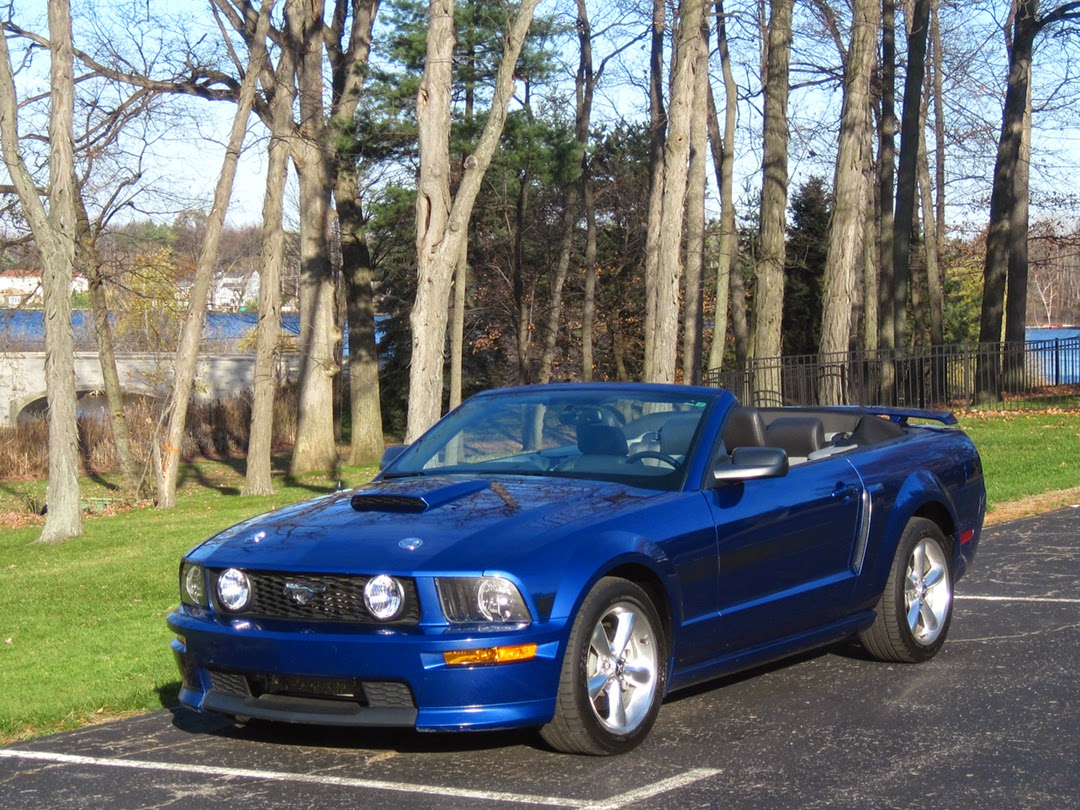
     I was fortunate enough to sell my 2008 Ford Mustang GT convertible in February.  I used the cash to pay down a LOT of credit card debt... and now I have the means to move forward!  I built some more parts shelves in the garage area, and I ordered the supplies I needed to finish my compressed air system and got to work.  It took a lot of orders and a bunch of trips to the hardware store, but by mid-March my system was plumbed, with seven different outlet points set up in three different rooms.  I used Maxline components supplied by Engineered Specialties, a RapidAir dealer in Wisconsin.
     At the compressor, I removed the quick-connect and added 1/2" plumbing that included a valve, a tee for tying in another compressor if required, and a 1/2" flexible hose whip to the water separator and the first filter/regulator.  From there, the air is split off in three directions.  The first goes to a tire inflation station by the garage entrance; the second goes to a painting station in the woodshop, and the third enters the main shop, where I made a perimeter loop with two painting stations and two regular air outlets.  The three painting stations have their own filter/regulators and high-flow plumbing.  I installed the pipe runs with proper slope to optimize condensate drainage, and most of the outlets are fed in a top-loop manner to diminish  the possibility of water pickup.  Here is a diagram of the finished system layout:

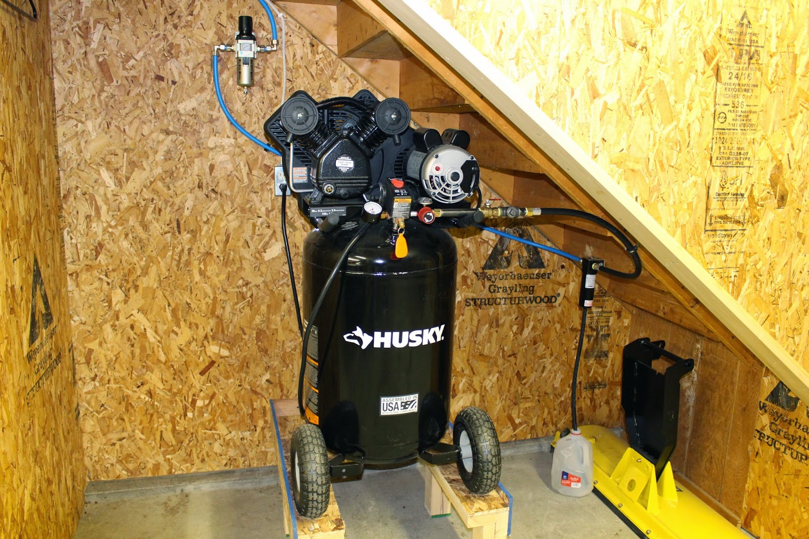
     This is where it starts; the compressor, separator and filter/regulator:

     The first split.  To the right goes through the wall to the main shop,
and to the left goes to the garage and wood shop.

     The second split, coming from the right into the manifold.  The upper loop goes to the wood shop, the left run goes to a tire filling station, and I used the remaining port for another quick connect point.

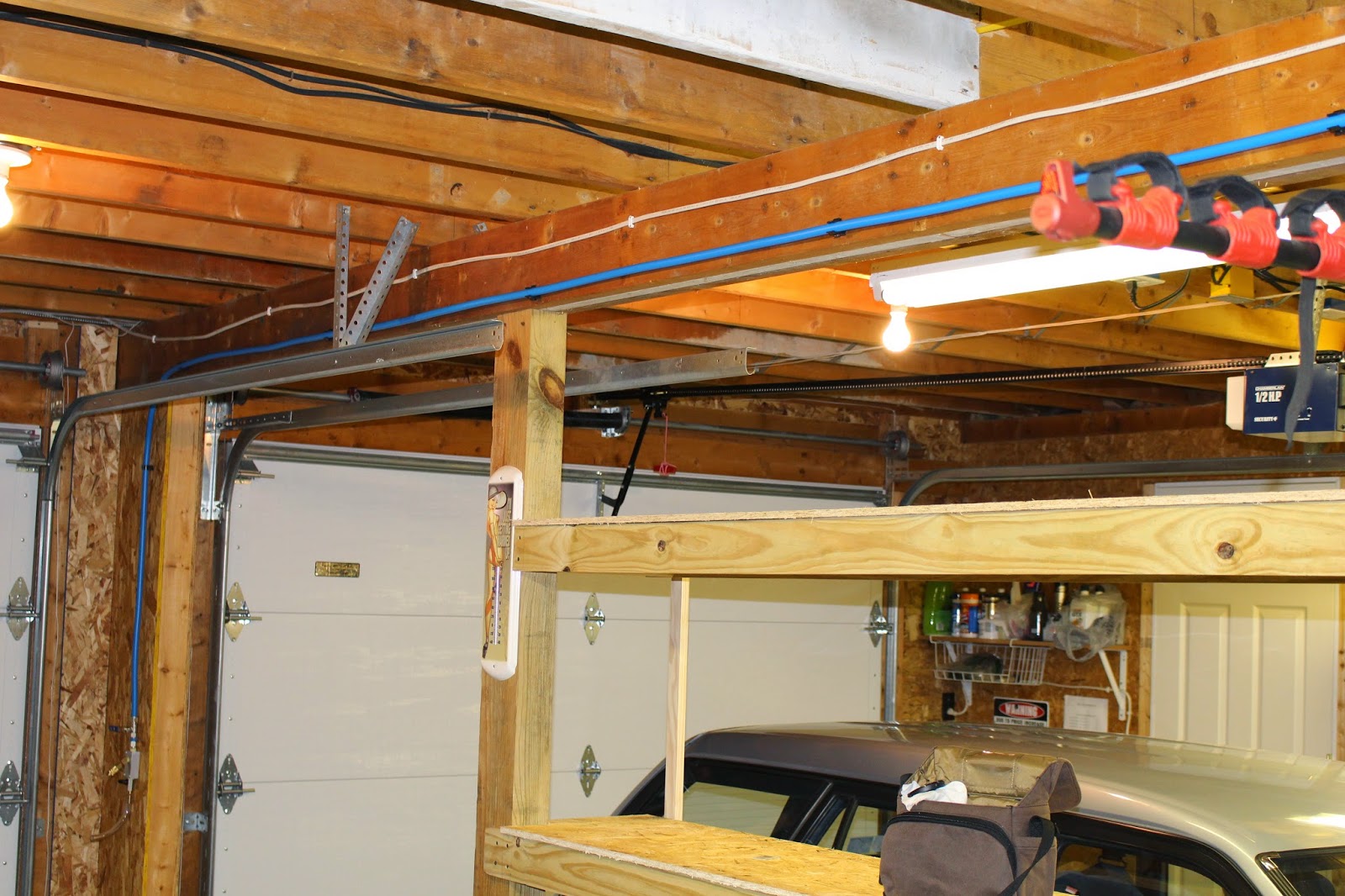
     This run goes to the tire filling station, where I can access vehicles in the garage, or outside, without having to add an outdoor connection.  I may add a hose reel to this station in the future.  This photo also shows some of the new parts shelves I put up in the garage area
     This is where the line from the manifold enters the wood shop.

     This is the painting station in the wood shop, with a dedicated filter/regulator.

     This is where the air enters the main shop, at a tee in the center of the picture just above the black pipe gas line stub, which will be used when I add a shop heater in the future.  The gas line stub is wrapped in paper toweling to keep the ever-stcky pipe sealant covered.  I needed to elevate the lines slightly from the center point for clearance issues; from the right & left corners on, the lines drop for condensate drainage.  The main painting station is visible in the right center of this view.  This also shows the two new 2'x8' folding work tables I purchased for the project.

     Moving clockwise around the room, this is the first rivet gun/air drill station, at the left end of the L-shaped attached workbench. 

     This is the second rivet gun/air drill station, at the right end of the workbench.  This is the lowest point in the main shop system, and the only one not fed from a top-loop tee, so if there's any condensate left in any lines after the separators and filters, it will probably drain from here.  All stations have their own drain valves attached at the bottom, and all will be drained after each use of the system.

     This is the second paint station in the main shop.  I'm not sure if this one was strictly necessary, but I thought as long as I was advised to set up the main shop as a loop system, I might as well have air stations on each wall; two for painting and two for rivet guns and drills.  Their use is probably interchangeable, but the demands of painting favor the plumbing, flow, filtering and regulation of the dedicated painting stations.  I'm hoping to find a better place to store the wrapped & rolled Persian rug in this photo by the time the big crates arrive.

     I've tested the system, and everything seems to work as planned.  With all the tees, elbows and other fittings involved in building this system, I only found one that I had not tightened properly.  It popped off quickly with no damage, and was easily reconnected and tightened.  The Maxline 1/2" air pipe is really nice to work with, and came together well.  The instructions state that the piping will expand slightly as ambient air temperature increases.  Since this system was set up in an as-yet-unheated building near the end of a never-ending Michigan winter, with record low temps for March, it will be interesting to see how much expansion might affect the long runs when it gets really hot.  I do have service bends and arcs built into the system, so hopefully those will accomodate the expansion without causing any undue bulging or sagging of the straight runs.
     This system does not contain any provision for in-line oiling.  I was advised to oil my rivet guns, drills and other air tools by merely putting a drop or two of pneumatic tool oil directly into the inlet of the tool before use.  This should lubricate it adequately, and this method keeps oil out of the air lines.  I may get a bit of compressor oil, but I'm thinking that should be removed by the separator and filters.  Most of that seems to accumulate in the air tank, and drains out with the bleed air as I vent the system after shutdown.  I'm hoping this will prove to be a non-issue.
     Compressed air systems can be very complicated and very costly, depending on what level of perfection you require.  I still have a lot to learn about the ins & outs, as it were... especially regarding painting.  But based on my current research, I think the system I've created here will be adequate for my needs.  Time, and much work, will tell.
     So I'm off and running... and someday, I'll be off and flying.  The next step is tooling up.  I'm looking at the Cleaveland Tool kit they've put together specifically for Van's RV builders as a starting point; I'll place that order next week.  And I've already prepped my Vans order form for my empennage; I'll be sending that in the next month.  It feels great to be making real progress again!

Wednesday, December 10, 2014

2014 Year In Review

     As expected, it has been a slow year for the project itself, but some more progress has been made in preparation.  In January, I wired a dedicated 110 volt circuit for an air compressor.  In March, I purchased a Husky 30 gallon air compressor from Home Depot.  After breaking it in, I realized it was rather difficult to get to the tank drain, so I built a platform to elevate it.  I also built the enclosure wall for the stairwell leading up to the loft, and insulated and covered the walls and ceiling of the stairwell. I left a gap between the enclosure wall and the stairs, thinking that it would provide ventilation for the compressor, allowing heat to escape up the stairwell and out of the ceiling vent.


     In May, I had the gas line continued from the stub-in at the exterior wall up to the future heater location, and enclosed all the remaining unfinished wall surfaces.  The detached garage structure is essentially finished off now, with the possible exception of some additional trim work I may or may not choose to do.  I did some additional research on compressed air systems, and figured out what else I would need to complete the system I’ve designed for my shop, including filtration, water/oil separation and plumbing. 
     In June, I took a long road trip that included visits to the Mid-Atlantic Air Museum and the National Museum of the United States Air Force.  And at the end of July, the curse was lifted, and I finally achieved my dream of flying into AirVenture in a warbird.  On Wednesday, July 30, I departed Willow Run in the Yankee Air Museum’s C-47, Yankee Doodle Dandy and flew to OSH for the day.  Since it was only a day trip, I hurried to see as much as I could in the time I had.  I took a lot of photos of some beautiful RV-8s, talked to a few owners, and generally stoked the fire.  It was a long, exhausting and fulfilling day.


     In August, our EAA Chapter 113 hosted the Ford Trimotor’s tour stop at PTK, and I volunteered as part of the ground crew.  I also assisted in one of the chapter’s many Young Eagles flying days.
     Waiting for the building process to begin has begun to feel like a prison sentence to me, so in late August I decided to try to sell my beloved 2008 Mustang GT California Special convertible in order to finance the tooling up and an early start to the project.  But alas, it seems that in Michigan it’s very easy to buy things, and very difficult to sell them.  The only offers I got were about half of what it is realistically worth, and I love the car too much to dump it for a low price.  So the wait continues.  Next spring, I will offer it for sale again, and keep it on the market until it sells.  In the meantime, I will see if I can set aside the funds to get the compressed air system plumbed.  And I’ll keep attending EAA meetings, reading blogs and magazine articles, watching YouTube videos and poring over my preplans again and again, psyching myself up for the day that this project truly begins in earnest.  If anyone out there wants to buy a great Mustang convertible, let me know.


Wednesday, January 1, 2014

Beginning of the last long layoff

     The first day of 2014 ushers in a new era of austerity for me.  Funding for anything other than keeping the bills paid will be hard to come by for the next 2+ years, so I'm not expecting much progress toward building my aircraft.  I will continue to be active with EAA Chapter 113 as much as time and gas money permit, and when any significant progress occurs, I will post it here.

Tuesday, July 2, 2013

2013 AirVenture Confirmed!

     Today I purchased my tickets for this year's Airventure.  This will only be my second time there; the first was in 2010, aptly named Sloshkosh because of the flooded grounds that year.  I was hoping to attend via the Yankee Air Museum's C-47, as I had planned to in 2011 and 2012, but for the third time in a row, it isn't going to happen.  In 2011, we couldn't take off from Willow Run because of severe thunderstorms; in 2012 they hadn't sold enough seats for the Thursday I was scheduled, and I couldn't change my travel plans.  This year the C-47 is going through some certification changes and modifications, so I made the commitment to drive to Oshkosh and camp on the airfield.  In 2010 I stayed for the full week, but I can't really afford to do that this year, so I'm planning to arrive Tuesday afternoon, set up camp, and attend the fly-in Wednesday thru Friday, and drive home sometime Saturday.  I thank my family for allowing me to make this trip as a combination Fathers Day & birthday present.
     I'll be attending a couple seminars, including Budd Davisson's tailwheel seminar. I've been a long-time fan of his aviation writing and we've corresponded via email on numerous occasions.  I met him at his AirVenture seminars in 2010, and I'm hoping to get a chance to chat with him again this year.  Another old friend from California will also be attending this year, and his Lockheed PV-2 Harpoon will be featured in Thursday's Warbirds in Review.  Taigh Ramey is a Beech 18 and Warbird specialist that operates Vintage Aircraft in Stockton, Ca.  He was an instructor at Palo Alto Airport when I learned to fly there in the '80s; he gave me a BFR and was my pilot for an air-to-air photo mission I did for the owner of a Bellanca Viking.  I also crewed for Taigh when we attended the last Madera Gathering of Warbirds in his SNB-1; we were scheduled to fly it to Oshkosh that year, but he sold the plane before we got the chance.  I've seen him various times since then, and it will be cool to get a chance to meet up at AirVenture. 
     I also hope to connect with other RV-8 enthusiasts that I've followed online.  I'm planning to spend a LOT of time in the RV parking area, taking tons of pictures and closely examining some excellent airplanes.  This trip should definitely help to keep me inspired to achieve my goal!

Thursday, May 9, 2013

Paint Booth Exhaust Fan Unit built

     Over the past few days, I built the exhaust fan unit that I'll use for ventilating the main shop when it's set up for painting.  As usual, I overbuilt the hell out of it... but it's a nice sturdy piece.  Unlike the workbench and shelving unit, I used woodworking glue, as well as screws and nails, for assembly.
     I started out by buying three 20" box fans and some lumber.  I had a sheet of 1/2" OSB on hand, so I ripped it lengthwise to get two 2x8 sheets.  I took the fan covers off, and used the inner perimeter of the fan frame to trace three opening outlines on an OSB sheet, which I cut out with a sabre saw.  I took the fan front screens and mounted them over the openings on the exterior side of the OSB, and mounted the fans themselves on the interior side.  I decided to augment the attachment of the front screens and fans with the use of some silicon sealant along the perimeter of each... but this proved to be a mistake.  As it turns out, the sealant tube, although never opened, was old enough to expire, and as a result it never set up after application... it remains gooey even now.  This issue was not critical enough to halt progress, however.  I wiped off as much excess as I could from the fixtures, and continued.


     I decided to use 2x6s for most of the unit's framework; although heavy, it provided the rigidity and substantial mounting surfaces I sought.  The top piece is 1x6.  The inital design was sketched, but actual construction details and dimensions were determined as the work progressed.  At first I had chosen 20"x20" filters for the design, but later changed those to 20"x25" for better air flow.  Once the frame was built onto the exterior OSB,  I cut out the six pieces of OSB that would comprise the interior surface, and assembled them as required.  Then I fabricated the filter framework out of 1x2 boards and attached them to the interior OSB.

     I attached grab handles to the interior side, to make this big, ungainly, heavy unit a bit easier to handle.  I ran the fan plug wires along the interior framework and out of a central exit slot.  I mounted a power strip to the interior trim, and tacked down the cord to keep it secure and out of the way.  I had removed the top handles from the fans, but left the four-position rotary switches intact in their stock location.  They are easily accessible thru the filter openings.  I experimented with different types of filters, and initially chose the pleated type.  These fit the openings best.  The second photo below shows the unit in place under the garage door, with a filler board inserted on the right side.

     And here is an exterior view of the installed unit; the first photo with the fans off, the second photo with the fans on.

     It occurs to me that the main source of incoming air in this configuration will be the gap along the top of the garage door opening that is created when the door is partially raised.  I'll have to insert some sort of screen or filter along that gap, so I won't be sucking in dust, pollen and bugs from the outside.  That should be easy to configure using the cheap green filters, or screens.  I also thought about a gap seal along the bottom of the fan unit... but an easier solution would be a long strip of carpet that would be laid down where the fan unit sits, compensating for the uneven apron surface.  Other sealing requirements around the edges may have to be addressed... and since it's so big and heavy, I'll have to put some thought into how I intend to store it when not in use.  But at least the unit is basically complete, and it moves a lot of air, so I'm happy with the result.  Another prep step complete!

Sunday, April 28, 2013

RV-8 Paint Schemes

     Not long after getting my pre-plans set, I got the three-way drawings out of the back of the binder, scanned them, and then started designing paint schemes using Photoshop.  Of course, being a warbird fan like many other builders, I decided to go with a pseudo-military paint scheme similar to that of a late-war WWII fighter.  My first designs incorporated a military silver base coat, with stars & bars, invasion stripes, a stars & stripes tail design, a checkerboard cowling, flat black non-reflective paint along the top of the nose, and a spiral nose cone.  The interior would be dull dark green, with the instrument panel done in a flat black wrinkle finish.  It would look something like this on the field:

     Although I really like the way this looks, there are two downsides.  First, there are a LOT of RV-8s out there that have similar paint jobs.  Second, doing something like this properly would involve an incredible amount of work, and probably the skills of a professional.  If I wanted to do the job myself (and I do), I'd be much better off going with a much simpler mid-war scheme of olive drab, with a neutral grey belly.  Not only would this be easier, but it would be more realistic than a showy high-gloss paint job, and I wouldn't have to worry so much about flaws and imperfections.  After all, there's a war on; we gotta get these things flying, right?  Here is that version in an airborne illustration:
     Another difference you may have noticed in this second drawing is the elimination of the carb scoop on the bottom of the cowling, since my aircraft will probably be fuel injected and use a different air source, as I've seen done on others.  I might put a spiral on the nose cone, or maybe paint it red.  Pardon the ridiculous looking pilot... but I'm not that great of a graphic artist... especially using Photoshop.  You may have noticed my nose art... here's a close-up view:


     I'd have to hire out to get this done right... as well as some more cool details I've seen on RVs, such as exhaust stacks and gun ports.  I'm pretty sure I'll finish the paint before the first flight... that's something else I'll want to research.  Some builders finish the paint before they fly, so that the aircraft weight/balance and control surface balancing are dialed in.  Others fly now and paint later.  In any case, that part of the project is a LONG ways off at this point... I'll paint that bridge when I come to it.
(design graphics copyright Clownbreath Industries 2013)


Shop Shelves

     I built the shelf unit last weekend.  A straightforward and relatively easy build; no glue, just good wood screws, and short nails for the OSB shelves.  This should work well for storing some of the larger kit pieces.  Shelf size is 8x2; height varies from shelf to shelf.  I figured it would be best to store the largest pieces low... almost 34' clearance on that bottom shelf.  I added the crossbraces a few days later, using plywood material I had on hand, and it's a nice rigid piece now.  Even thinking of adding casters, but it's really not all that heavy, so it shouldn't be hard to move about when necessary.